Modeling Method of Ordered Binary Decision Diagram for Distribution Network Fault Restoration
A binary decision diagram and distribution network fault technology, applied to electrical components, circuit devices, emergency protection circuit devices, etc., can solve problems such as long calculation time, difficulty in ensuring recovery effect, and difficulty in meeting the requirements of rapid fault recovery
- Summary
- Abstract
- Description
- Claims
- Application Information
AI Technical Summary
Problems solved by technology
Method used
Image
Examples
Embodiment 1
[0043] Such as figure 2 As shown, it is the distribution network diagram used in this embodiment. The distribution network has 33 nodes in total, the active load is 3,715kW, the reactive load is 2,300kVar, and node 1 is a slack node. 12.66kV, the power reference value is 10MVA). There are switches on each branch, that is, the number of switches is equal to the number of branches, figure 2 In , the solid line represents the branch circuit equipped with isolating switch, and the dotted line represents the tie line equipped with tie switch. In this example, it is assumed that there is a failure near 9 nodes.
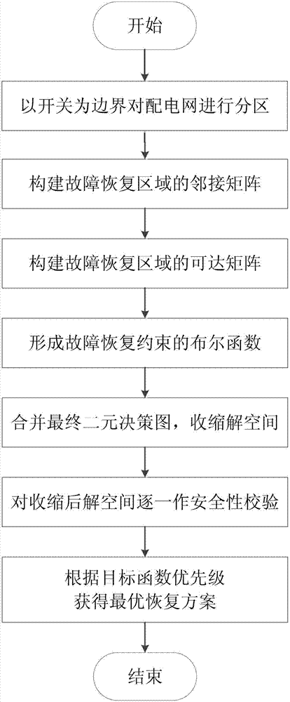
[0044] Such as figure 1 As shown, it is a control flow chart of the ordered binary decision-making graph modeling method for distribution network fault recovery of the present invention, and the specific flow of its control is as follows:
[0045] (1) If there is a fault near node 9, the section switch 8-9, 9-10 is disconnected to automatically isolate the fault, and ...
Embodiment 2
[0070] In this embodiment, except for the following features, all the other features are the same as those in Embodiment 1: a failure near node 5 is established, and the spare capacity of the tie switch is set to 480kVA. The specific operation steps are as follows:
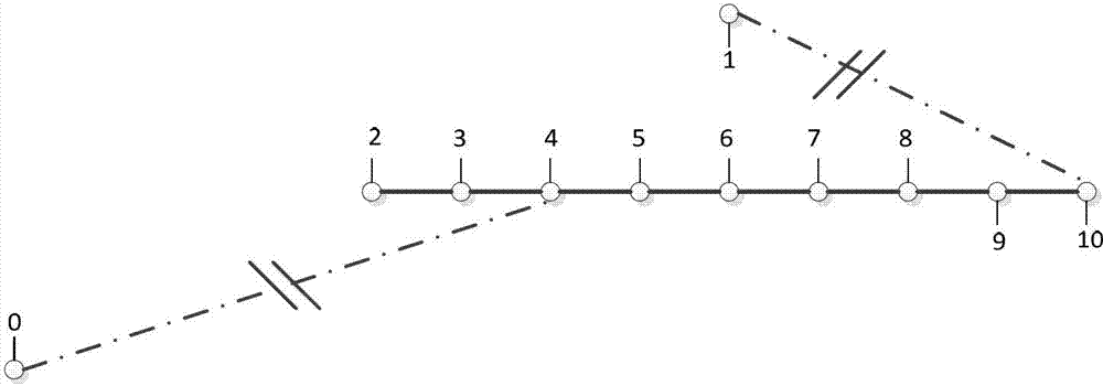
[0071] (1) When there is a fault near node 5, the section switches 4-5 and 5-6 are disconnected to isolate the fault. There are 21 non-fault outage areas, with a total of 20 section switches and 4 contact switches. Therefore, there are 24 decision variables, and the other side of the tie switch is equivalent to a power node, and renumbered together with the non-fault blackout area, as Figure 4 shown;
[0072] (2) Form an adjacency matrix:
[0073]
[0074] (3) Use the WarShall algorithm to form a reachability matrix P;
[0075] (4) Form various constraints:
[0076] a) Form a power constraint C 1 ,
[0077] Since the other side of the tie switch is equivalent to the power supply, the constraint can be exp...
PUM
 Abstract
Description
Claims
Application Information
 - R&D
- Intellectual Property
- Life Sciences
- Materials
- Tech Scout
- Unparalleled Data Quality
- Higher Quality Content
- 60% Fewer Hallucinations
Browse by: Latest US Patents, China's latest patents, Technical Efficacy Thesaurus, Application Domain, Technology Topic, Popular Technical Reports.
© 2025 PatSnap. All rights reserved.Legal|Privacy policy|Modern Slavery Act Transparency Statement|Sitemap|About US| Contact US: help@patsnap.com


