
Microfluid-based self-breathing photocatalytic film-free fuel battery

A fuel cell and self-breathing technology, which is applied in the direction of fuel cells, circuits, electrical components, etc., to achieve the effect of convenient manufacturing, low cost, and reduced manufacturing costs

Inactive Publication Date: 2013-07-10
EAST CHINA UNIV OF SCI & TECH +1
View PDF3 Cites 24 Cited by
  • Summary
  • Abstract
  • Description
  • Claims
  • Application Information

AI Technical Summary

Problems solved by technology

Currently, there are no reports of photocatalytic fuel cells designed using gas diffusion electrodes

Method used


Image

  • Microfluid-based self-breathing photocatalytic film-free fuel battery
  • Microfluid-based self-breathing photocatalytic film-free fuel battery
  • Microfluid-based self-breathing photocatalytic film-free fuel battery

Examples


Embodiment 1

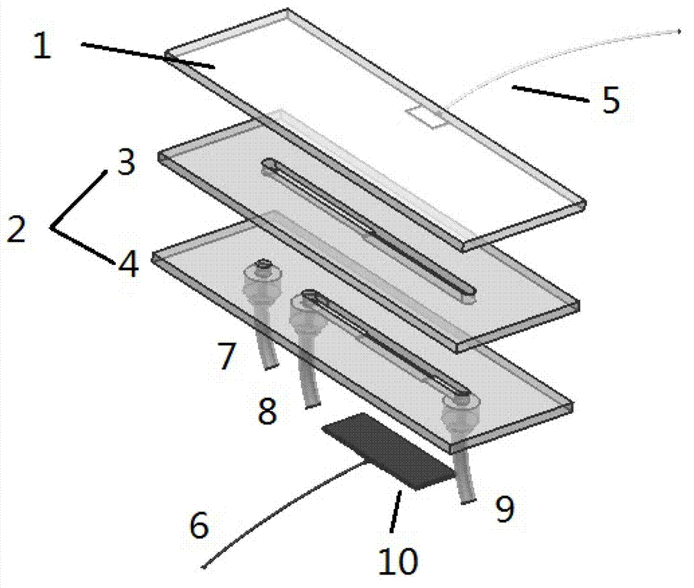
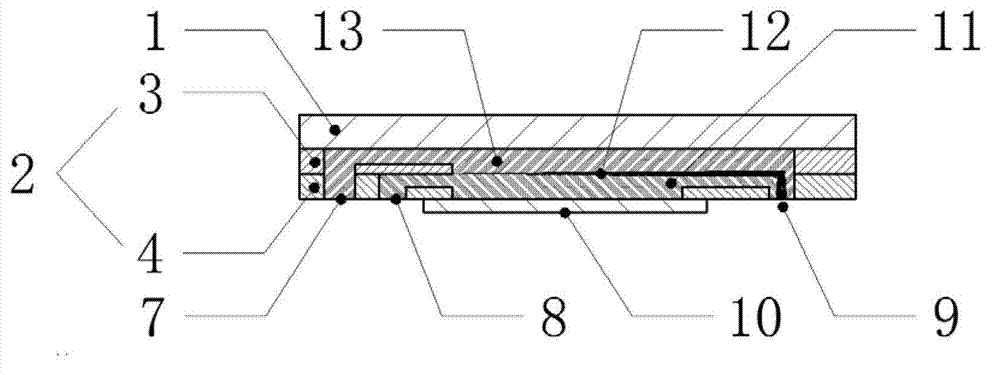
[0035] exist figure 1 Among them, the photocatalyst-loaded conductive glass 1 and the battery chip 2 constitute the main body of the microfluidic photocatalytic membraneless fuel cell. Two sections of grooves and two through holes are engraved on the substrate I3, the front section is a groove (length 16mm, width 2mm, depth 0.4mm), the rear section is a through groove (length 17mm, width 2mm, depth 0.5mm), the groove and The photocatalyst-loaded glass is bonded to form the anode inlet channel, the through groove and the through groove of the substrate II4, the conductive glass and the gas diffusion electrode 10 are bonded to form the battery micro flow channel. There are three sections of grooves and three holes engraved on the base plate II, and the front and rear sections (the entrance end is the front, the exit end is the back) are grooves (the front section is 8mm long, 2mm wide, and 0.4mm deep; the rear section is 7mm long, 2mm wide, and deep 0.4mm), the middle section i...


PUM

PropertyMeasurementUnit
widthaaaaaaaaaa
current densityaaaaaaaaaa

Abstract

The invention relates to a microfluid-based self-breathing photocatalytic film-free fuel battery. The microfluid-based self-breathing photocatalytic film-free fuel battery is characterized in that conductive glass, a microfluid battery chip and a gas dispersing electrode form a main body of the micro-flow photocatalytic film-free fuel battery; the conductive glass is loaded with a titanium dioxide semiconductor nanorod serving as a photocatalyst; an anode conductor and a cathode conductor are used for leading out electric energy generated from the interior of the battery for external electric appliances to use; and organic waste water pollutant and anode electrolyte respectively flow in from an anode liquid inlet and a cathode liquid inlet. The microfluid-based self-breathing photocatalytic film-free fuel battery removes a proton exchange membrane required by a traditional photocatalytic fuel battery by a principle of laminated flow of microfluid laminar flow so as to simplify the battery structure and reduce the manufacturing cost; oxygen of air enters the battery chip through the gas dispersing electrode to participate in reaction without a special conveying device; and the waste water pollutant and the anode electrolyte are injected into the photocatalytic fuel battery chip through a micro-flow pump, and chemical energy of the organic pollutant is transformed into electric energy which is output outwards.

Description

【Technical field】 [0001] The invention relates to the technical field of fuel cells, in particular to a microfluid-based self-breathing photocatalytic membraneless fuel cell. 【Background technique】 [0002] The photoelectrochemical reaction is to use light energy as energy input to promote the electrochemical reaction, so that the chemical energy stored in the chemical substance is converted into electrical energy and output. [0003] When the photocatalyst in the photocatalytic fuel cell is irradiated by light radiation, the semiconductor photocatalyst is excited, releasing electrons and generating holes at the same time. The released electrons and holes can react with water to generate strong oxidizing free radicals, which can decompose organic pollutants in wastewater. The electrons generated by excitation can also be exported through the external circuit to form a current to supply power to the external circuit. [0004] The current photocatalytic fuel cell adopts a bu...

Claims


Application Information

Patent Timeline
Patent Type & Authority Applications(China)
IPC IPC(8): H01M8/22
CPCY02E60/50
Inventor 宣晋梁国熙张浩徐宏张莉王慧至王滨
Owner EAST CHINA UNIV OF SCI & TECH
Learn More