
Method for increasing responding speed of phase only liquid crystal on silicon device

A silicon-based liquid crystal, response speed technology, applied in static indicators and other directions, can solve the problem of slow response speed of phase-controlled silicon-based liquid crystal devices

Active Publication Date: 2013-07-10
TSINGHUA UNIV
View PDF6 Cites 7 Cited by
  • Summary
  • Abstract
  • Description
  • Claims
  • Application Information

AI Technical Summary

Problems solved by technology

[0022] The technical problem to be solved by the present invention is to provide a method for improving the response speed of phase-controlled silicon-based liquid crystal devices to solve the problem of slow response speed of phase-controlled silicon-based liquid crystal devices in the prior art

Method used

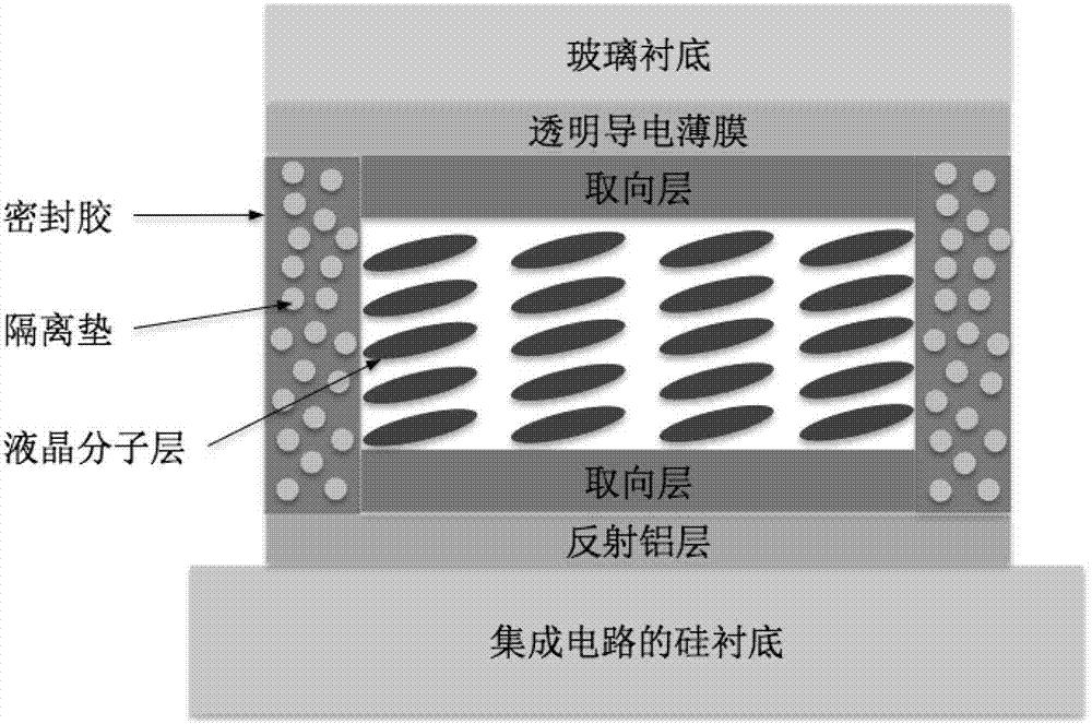
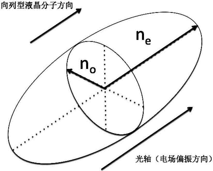
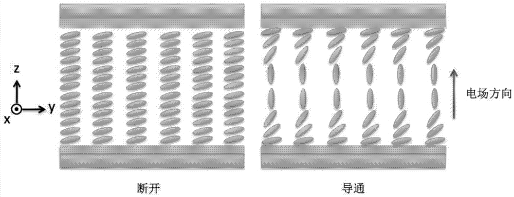

Image

  • Method for increasing responding speed of phase only liquid crystal on silicon device
  • Method for increasing responding speed of phase only liquid crystal on silicon device
  • Method for increasing responding speed of phase only liquid crystal on silicon device

Examples


Embodiment 1

[0058] The embodiment of the present invention relates to a method for improving the response speed of a phase-controlled silicon-based liquid crystal device: comprising:

[0059] Step S101, increasing the driving voltage to the maximum load voltage Vmax, and completing the maximum voltage driving process;

[0060] In this step, the maximum voltage of the phase-controlled LCOS device driven by the analog circuit is generally around 7V, and the gray scale ranges from 0 to 255; that is, the voltage gradient is divided into 256 levels, and the variation of each level of voltage is (7 / 255) V. According to the description in the previous paragraph, it is assumed that the normal response time of the device should be t i , that is, the response time when the load voltage gray level (N) is i. In the current driving method, the device responds the fastest when adjusting the full phase (2π) value, that is, the moment when the maximum voltage load is applied to the device. According ...

Embodiment 2

[0084] Considering the error of the production process and the error of the optical environment, under normal circumstances, the thickness of the liquid crystal on silicon device will be larger than the required requirement, the working range of the device reaches 2π, and the manufacturing thickness of the device is often slightly higher than the required value; generally 2.5π, or even 3π. This not only ensures the working performance of the device, but also makes the full-phase debugging range more flexible. According to this feature, in the embodiment of the present invention, the interval of the working range is modified, and the original (0, 2π) is shifted to (m, 2π+m), where m is the adjustment step. The purpose of doing this is to improve the slow response of low voltage while keeping the working range unchanged.

[0085] The embodiment of the present invention relates to a method for improving the response speed of a phase-controlled silicon-based liquid crystal device...


PUM

PropertyMeasurementUnit
thicknessaaaaaaaaaa

Abstract

The invention discloses a method for increasing the responding speed of a phase only liquid crystal on silicon (LCOS) device. The method comprises the following steps: S101, increasing the driving voltage to the maximum load voltage Vmax and finishing the maximum voltage driving process; S102, reducing the driving voltage to the target voltage value Vi determined by the working temperature of the device to realize the expectant target phase value, wherein the required time of the device at the moment is td_i, the td_i is the responding time from the maximum voltage to the gray scale i, and the i=0, 1, 2, ..., 255; and S103, obtaining the final phase delay. The method adopts an electrically controlled birefringence (ECB) mode to fulfill the aim of increasing the speed of the device on the basis of meeting the original advantages of continuous phase debugging, extremely low quantized error, high optical transmission efficiency, all phase debugging and the like.

Description

technical field [0001] The invention relates to the technical field of liquid crystal display, in particular to a method for improving the response speed of a phase-controlled silicon-based liquid crystal device. Background technique [0002] LCOS (Phase Only Liquid Crystal On Silicon) technology has been developed in image and video display for nearly 20 years. Unlike traditional LCD (Liquid Crystal Display, liquid crystal display) flat panel display technology, it not only utilizes The unique photoelectric characteristics of liquid crystal materials combine the advantages of high-performance and multifunctional CMOS (Complementary Metal Oxide Semiconductor, Complementary Metal Oxide Semiconductor) integrated circuits, and use electrical signals to control the deflection of liquid crystal materials. The full-phase and continuous debugging of light is the best for the utilization efficiency of light from the principle point of view. Therefore, the application function of th...

Claims


Application Information

Patent Timeline
Patent Type & Authority Applications(China)
IPC IPC(8): G02F1/133
Inventor 张紫辰尤政初大平
Owner TSINGHUA UNIV
Learn More