Hydraulic tunnel inverted arch operation trolley and inverted arch construction method

A workbench and tunnel technology, applied in tunnels, tunnel linings, earthwork drilling, etc., can solve the problems of large labor input, discount of formwork support, formwork offset, etc., to reduce labor intensity, improve quality, and improve progress. Effect

Active Publication Date: 2013-07-10
湖南远东钢模有限公司
View PDF12 Cites 15 Cited by
  • Summary
  • Abstract
  • Description
  • Claims
  • Application Information

AI Technical Summary

Problems solved by technology

[0004] When using the above-mentioned inverted arch operation trolley to construct the inverted arch, since the various formworks are connected and integrated in a fixed connection, the formwork is difficult to locate when in use, and after the invert arch is constructed once, the formwork It needs to be disassembled and assembled as a whole to facilitate the next construction operation, so the labor input is large and the efficiency is low; in addition, the bearing capacity of the existing inverted arch formwork is not large enough, so that the length of the inverted arch in one construction is shorter and the extension The construction time of the inverted arch is shortened; and because the bearing capacity is not large enough, the entire inverted arch formwork is easily deformed during the inverted arch construction process, which greatly reduces the supporting effect on the formwork and easily causes the formwork to shift, thereby affecting the construction of the inverted arch quality after

Method used


Image

  • Hydraulic tunnel inverted arch operation trolley and inverted arch construction method
  • Hydraulic tunnel inverted arch operation trolley and inverted arch construction method
  • Hydraulic tunnel inverted arch operation trolley and inverted arch construction method

Examples


Embodiment Construction

[0023] The present invention will be further described below in conjunction with the accompanying drawings.

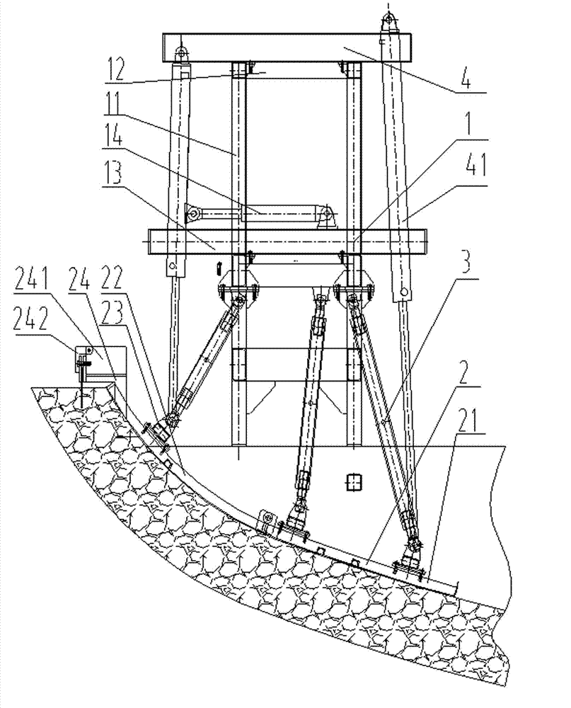
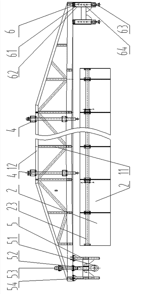
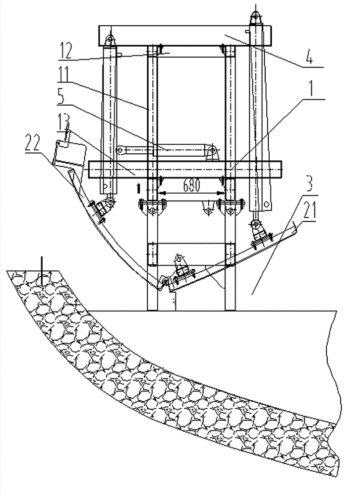
[0024] Such as figure 1 , 2 As shown, the present invention includes a main beam 1, a plurality of templates 2 and three rows of screw mandrels 3, each of the templates 2 includes a first template 21 and a second template 22, the first template 21 and the second template 22 are hinged, and multiple Two templates 2 are connected as a whole in a hinged manner; the main beam 1 includes a cross beam 12 and a vertical support 11, and the cross beam 12 and the vertical support 11 are fixedly connected as one; the upper end of the main beam 1 is provided with Two tailstocks 4, the two ends of each tailstock 3 are respectively hinged with the upper end of a lifting cylinder 41, and the lower end of the lifting cylinder 41 is hinged with the corresponding template 2 respectively. The main beam 1 is also provided with two control frames 13 corresponding to the two tailstocks 4...


PUM


Abstract

The invention discloses a hydraulic tunnel inverted arch operation trolley and an inverted arch construction method. The hydraulic tunnel inverted arch operation trolley comprises a main beam, a plurality of templates and at least three rows of screw rods, wherein each of the templates comprises a first template body and a second template body, first template bodies are hinged with second template bodies, the plurality of templates are connected into a whole in a hinge mode, two tailstocks are arranged on the upper end of the main beam, two ends of each of the tailstocks are hinged with upper ends of two lifting oil cylinders respectively, lower ends of the two lifting oil cylinders are hinged with corresponding templates respectively, two control frames are arranged at positions on the main beam, which correspond to the two tailstocks, control frames are hinged with one end of a translation oil cylinder, the other end of the translation oil cylinder is hinged with the lifting oil cylinder which is located at the same end as the two tailstocks, lower ends of the three rows of screw rods are hinged with two ends and middle portions of templates respectively, and upper ends of the three rows of screw rods are hinged with the main beam. The hydraulic tunnel inverted arch operation trolley is simple to operate and capable of accelerating the construction schedule of a tunnel inverted arch and improving the quality of inverted arch construction.

Description

technical field [0001] The invention relates to a hydraulic tunnel inverted arch operation trolley and an inverted arch construction method used in highway, water conservancy, and railway tunnel projects. Background technique [0002] The inverted arch is one of the main components of the tunnel structure, and it is the lining foundation commonly used in tunnel construction at present. On the one hand, it must effectively transmit the pressure of the upper formation of the tunnel and the load on the road surface to the underground through the tunnel side wall structure, and on the other hand, it must also effectively resist the reaction force from the lower formation, so the inverted arch has a great impact on the stability of the entire tunnel It plays a vital role. Therefore, the inverted arch construction of the tunnel has become an important link in the entire tunnel construction process, and in the inverted arch construction process, the inverted arch operation trolley...

Claims


Application Information

Patent Timeline
Patent Type & Authority Applications(China)
IPC IPC(8): E21D11/10
Inventor 瞿伦建沈承福刘江涛李可军
Owner 湖南远东钢模有限公司
Why Eureka
Try Eureka