Eureka AIR delivers breakthrough ideas for toughest innovation challenges, trusted by R&D personnel around the world.

Synchronous rotating mechanism for shuttle race

A technology of synchronous rotation and shuttle bed, applied in the direction of sewing machine ring mechanism, sewing machine components, sewing machine needle seat, etc., can solve the problems of not meeting the requirements, low product pass rate, affecting the overall quality of the product, etc., to improve the appearance Aesthetics, wide use value, effect of improving sewing quality

Active Publication Date: 2013-07-10
ANHUI JIEYU SHOEMAKING MACHINERY TECH CO LTD +1
View PDF6 Cites 3 Cited by
  • Summary
  • Abstract
  • Description
  • Claims
  • Application Information

AI Technical Summary

Problems solved by technology

[0002] The traditional sewing mechanism generally includes an upper casing and a lower casing, an upper shaft motor and a needle bar mechanism installed on the upper casing, and an upper shaft motor and a needle bar mechanism that are respectively connected to the upper shaft motor and the needle bar mechanism in the upper casing. Shaft, as well as the lower shaft motor and the shuttle bed mechanism installed on the lower casing, are formed by the lower shaft which is installed in the lower casing and is respectively connected with the lower shaft motor and the shuttle bed transmission. The upper shaft is driven by the upper shaft motor to rotate, and the upper shaft The shaft drives the needle bar mechanism to move up and down to realize the up and down sewing action of the sewing needle. The lower shaft motor drives the lower shaft to rotate, and the lower shaft drives the shuttle bed mechanism to move to cooperate with the sewing needle for sewing operations. At this time, the shuttle bed cannot realize the corresponding rotation according to the sewing line at the same time
[0003] When the sewing machine is sewing, because the feeding mechanism will generate a certain thrust on the material to be sewn during the feeding process, and the thrust will also act on the bottom thread and the upper thread, causing the bottom thread and the upper thread to be twisted, and because The needle bar and shuttle bed of the existing sewing mechanism cannot be rotated, so affected by the push and pull of the feeding mechanism when feeding, the force on the bottom thread and the upper thread is unbalanced when sewing at the thread hook position, and the sewing direction of the sewing needle cannot meet the set requirements. The sewing stitches are consistent, which eventually leads to loose, uneven, uneven stitches and other defects
Especially when sewing irregular stitches, it is difficult for the stitching direction of the sewing needle to be consistent with the stitches set to be sewn, resulting in very loose, uneven, and uneven stitches that cannot be matched with Setting the stitches to be sewed to be completely consistent will seriously affect the appearance of the product and the sewing quality, and affect the overall quality of the product, resulting in a low pass rate of the product
[0004] Along with the raising of people's quality of life, people also more and more higher to the quality requirement of sewing, so above-mentioned existing sewing machine obviously does not meet the needs of today's society, urgently needs to be further improved

Method used


Image

  • Synchronous rotating mechanism for shuttle race
  • Synchronous rotating mechanism for shuttle race
  • Synchronous rotating mechanism for shuttle race

Examples


Embodiment Construction

[0015] The following best examples of the shuttle bed synchronous rotation mechanism of the present invention do not limit the protection scope of the present invention.

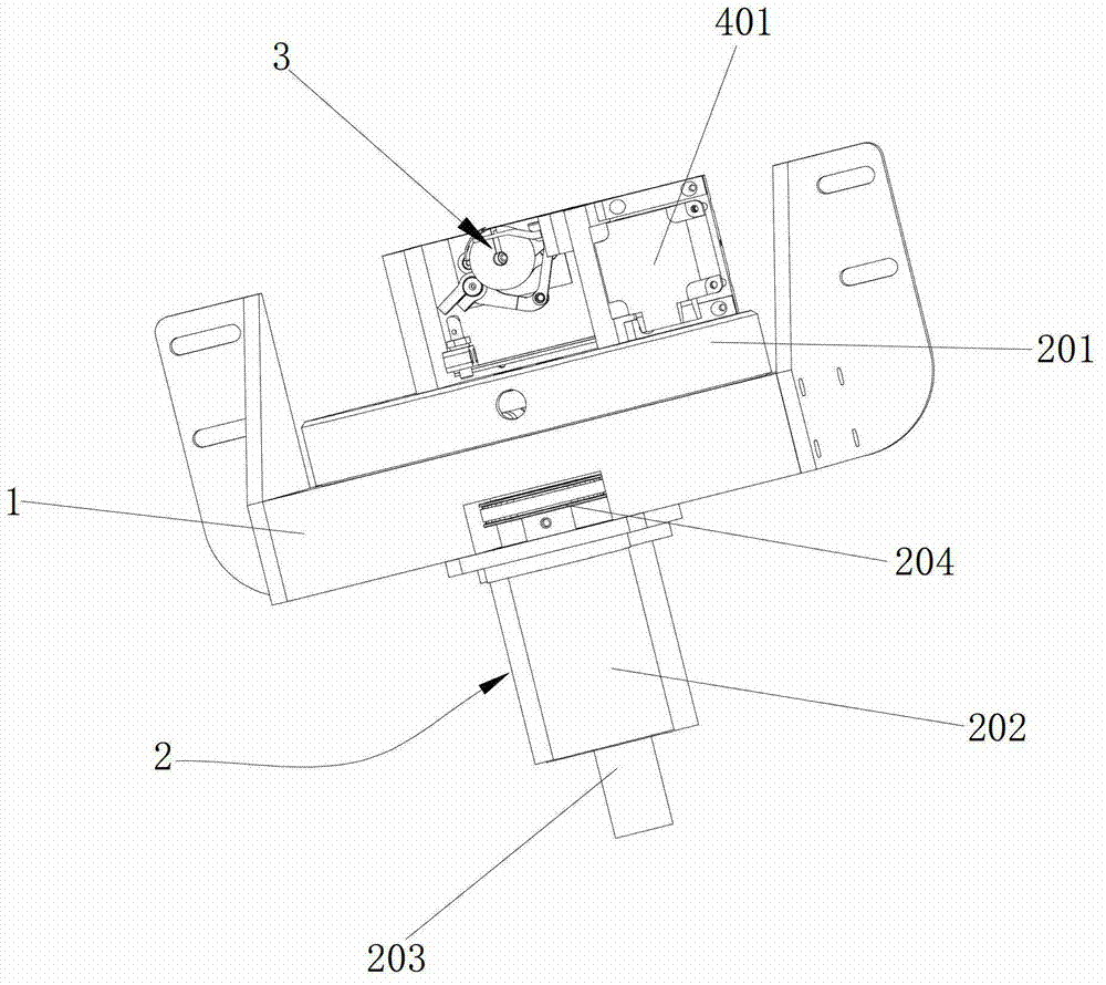
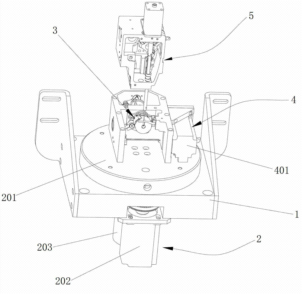
[0016] refer to figure 1 , figure 2 , image 3 , Figure 4 , providing a shuttle bed synchronous rotation mechanism, including a base 1, a rotating device 2 mounted on the base 1, a shuttle bed 3 mounted on the rotating device 2 and capable of rotating with the rotating device 2, and a shuttle bed driving mechanism 4. The shuttle bed drive mechanism 4 is in transmission connection with the shuttle bed 3 . By installing the shuttle bed driving mechanism 4 and the shuttle bed 3 on the rotating device 2, the rotating device 2 can drive the shuttle bed driving mechanism 4 and the shuttle bed 3 to rotate simultaneously, thereby realizing the shuttle bed 3 during sewing. Adaptive rotation can be carried out according to the stitch direction, so as to adjust the angle of the shuttle bed 3 to adapt to the set s...


PUM


Abstract

The invention discloses a synchronous rotating mechanism for a shuttle race. The synchronous rotating mechanism comprises a base, a rotating device installed on the base, the shuttle race and a shuttle race drive mechanism, wherein the shuttle race and the shuttle race drive mechanism are arranged on the rotating device, capable of rotating along with the rotating device and in transmission connection, so that the shuttle race can rotate when a sewing mechanism sews materials. In the material sewing process of the sewing mechanism provided with the synchronous rotating mechanism, the rotating device can drive a rotary table to rotate correspondingly according to the stitch direction so as to drive the shuttle race to rotate correspondingly according to the stitch direction and be matched with a needle bar synchronous rotating mechanism for synchronous rotation, so that the stitching direction of a sewing needle is accordant with preset sewed stitches, high-quality and perfect sewing is achieved, stitches obtained through sewing have the advantages of being compact, neat, even and perfectly coincide with the set sewed stitches, the practicability is high, and wide industrial utilization values are provided.

Description

technical field [0001] The present invention relates to the technical field of sewing machines, more specifically, relates to a needle bar synchronous rotation mechanism that can cooperate with the needle bar on the sewing machine to rotate synchronously, so as to realize the synchronous rotation of the shuttle bed and the needle bar, so that the sewing direction of the sewing needle is consistent with the sewing direction of the sewing machine. The shuttle bed synchronous rotation mechanism is set to keep the stitches to be sewed consistently. Background technique [0002] The traditional sewing mechanism generally includes an upper casing and a lower casing, an upper shaft motor and a needle bar mechanism installed on the upper casing, and an upper shaft motor and a needle bar mechanism that are respectively connected to the upper shaft motor and the needle bar mechanism in the upper casing. Shaft, as well as the lower shaft motor and the shuttle bed mechanism installed on...

Claims


Application Information

Patent Timeline
Patent Type & Authority Applications(China)
IPC IPC(8): D05B57/30D05B55/14
Inventor 王漫江
Owner ANHUI JIEYU SHOEMAKING MACHINERY TECH CO LTD
Why Eureka
Eureka Blog
Learn More