Touch control LED circuit and touch control LED head lamp

An LED circuit and touch control technology, applied in energy-saving control technology, electric lamp circuit arrangement, electric light source, etc., can solve the problems of poor contact, frequent maintenance, easy corrosion, etc., to reduce maintenance loss, prolong the life of lamps, and avoid easy damage. Effect

Inactive Publication Date: 2013-07-03
OCEANS KING LIGHTING SCI&TECH CO LTD +1
View PDF2 Cites 7 Cited by
  • Summary
  • Abstract
  • Description
  • Claims
  • Application Information

AI Technical Summary

Problems solved by technology

[0003] One problem with this type of headlight is that both the switch and the rubber button are easily damaged. If the light touch switch is pressed too many times, it is easy to have poor contact or even fail, while the rubber button is easy to break, and it is easy to corrode when encountering oil stains. Therefore, this kind of switch Poor durability, frequent maintenance

Method used


Image

  • Touch control LED circuit and touch control LED head lamp
  • Touch control LED circuit and touch control LED head lamp
  • Touch control LED circuit and touch control LED head lamp

Examples


Embodiment Construction

[0025] In order to enable those skilled in the art to better understand the technical solutions of the present invention, a further detailed description will be given below with reference to the accompanying drawings and embodiments.

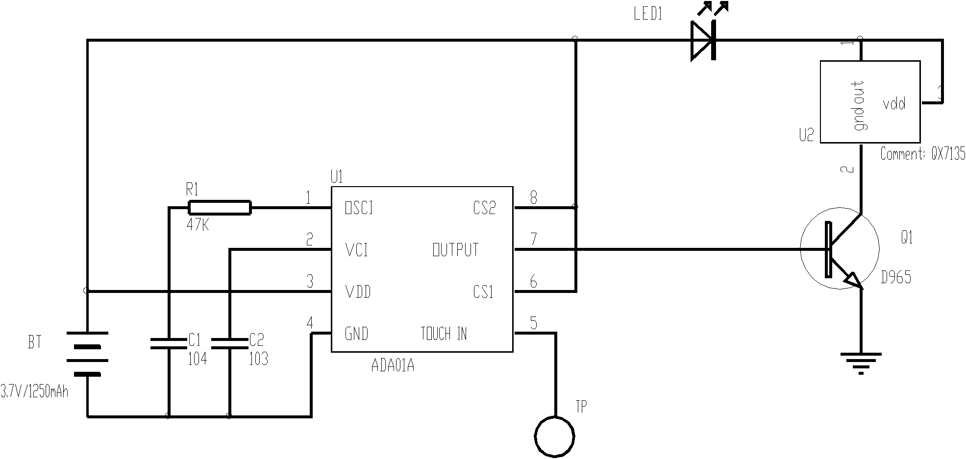
[0026] The electrical principle of the touch control LED circuit and the touch control LED headlight of the present invention is as follows image 3 As shown, a touchpad that senses touch information is used to replace the existing tact switches and rubber buttons.

[0027] The touch control LED circuit of the present invention includes: a touch panel TP for sensing touch information, a touch control unit U1, a transistor Q1, an LED light source LED driven by the transistor, a constant current module and a DC power supply;

[0028] The touch panel TP is connected to the signal input terminal TOUCH IN of the touch control unit U1, and the output control terminal of the touch control unit U1 is connected to the base of the transistor Q1; the collector of ...


PUM


Abstract

The invention discloses a touch control LED (light-emitting diode) circuit which comprises a touch panel (TP) for sensing touch information, a touch control unit, a triode connected with the touch control unit, an LED light source driven by the triode, a constant current module and a direct current power supply, wherein an input end of the touch control unit is connected with the TP; the TP is connected with a signal input end of the touch control unit; an output control end of the touch control unit is connected with a base of the triode; a collector of the triode successively passes through the constant current module and the LED light source to be connected with the direct current power supply; an emitter of the triode is earthed; and the touch control unit controls a working state of the LED light source according to touch times and touch time of the TP. The invention further provides a touch control LED head lamp. The touch control LED circuit and the touch control LED head lamp adopt a long-lived switching mode to substitute a light touch switch and a rubber button, so that the life of a luminaire can be prolonged effectively, and maintenance losses can be reduced.

Description

Technical field [0001] The present invention relates to the technical field of lighting signal lamps, in particular to a touch control LED circuit and a touch control LED head lamp. Background technique [0002] figure 1 Shown is a structural diagram of a prior art headlamp, figure 2 Is its electrical schematic diagram. It can be seen from the figure that this is an integrated headlamp. The lamp holder 1 and the battery box 2 are connected together. The switch 3 of the headlamp uses a light touch switch, which can be pressed through an external rubber button. [0003] One problem with this headlamp is that the switch and the rubber button are easily damaged. If the touch switch is pressed more times, it is prone to poor contact or even failure. The rubber button is easy to break, and it is easy to corrode when encountered with oil. Poor durability and frequent maintenance. Summary of the invention [0004] The technical problem to be solved by the present invention is to solve th...

Claims


Application Information

Patent Timeline
Patent Type & Authority Applications(China)
IPC IPC(8): H05B37/02F21S9/02F21Y101/02F21Y115/10
CPCY02B20/40
Inventor 周明杰邵贤辉
Owner OCEANS KING LIGHTING SCI&TECH CO LTD
Why Eureka
Try Eureka