EGR valve and waste gas recirculation system

An EGR valve and exhaust gas technology, applied in the direction of exhaust gas recirculation, charging system, engine components, etc., can solve the problems of EGR valve damage, hindering the opening of the valve plate 3', increasing the load of the motor and the risk of motor damage, etc., to achieve control Fast response, extended service life, and avoid the effect of easy damage

Inactive Publication Date: 2018-12-21
WEICHAI POWER CO LTD
View PDF8 Cites 1 Cited by
  • Summary
  • Abstract
  • Description
  • Claims
  • Application Information

AI Technical Summary

Problems solved by technology

Especially when the opening of the valve plate 3' is small and the gap between the valve plate 3' and the valve seat 2' is small, this vibration will cause the valve plate 3' and the valve seat 2' to be in a high-frequency impact state, It is easy to cause damage to the EGR valve, making the control responsiveness, control stability and reliability of the EGR valve low
[0006] Secondly, the thrust generated by the exhaust gas hitting the valve plate 3' will hinder the opening of the valve plate 3', increasing the driving torque of the motor when the EGR valve is opened, thereby increasing the load on the motor and the risk of damage to the motor

Method used


Image

  • EGR valve and waste gas recirculation system
  • EGR valve and waste gas recirculation system
  • EGR valve and waste gas recirculation system

Examples


Embodiment Construction

[0033] The technical solutions of the present invention will be further described below in conjunction with the accompanying drawings and through specific implementation methods.

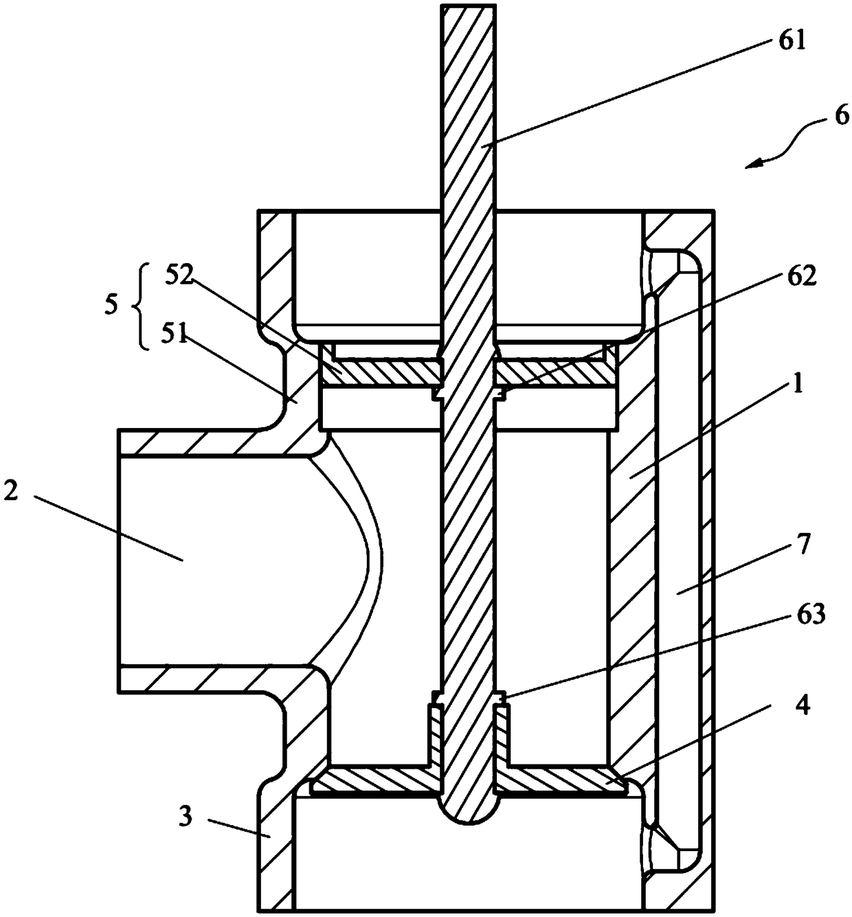
[0034] This embodiment provides an EGR valve, such as image 3 As shown, the EGR valve includes a valve body 1, an air outlet pipe 2 arranged on the outer wall of the valve body 1, a main valve seat 3 arranged at one end of the valve body 1, a main valve plate 4 arranged inside the main valve seat 3, and an auxiliary valve The valve plate 52 and the drive assembly 6, the auxiliary valve plate 52 can slide sealingly along the valve body 1, the auxiliary valve plate 52 divides the valve body 1 into the first working chamber and the second working chamber, the first working chamber and the main valve The seat 3 is connected, and the second working chamber is formed between the auxiliary valve plate 52 and the main valve plate 4; at the same time, the output ends of the drive assembly 6 are respectively...


PUM


Abstract

The invention belongs to the technical field of engines, and discloses an EGR valve and a waste gas recirculation system. The EGR valve comprises a valve body, an air outlet pipe arranged on the outerwall of the valve body, a main valve base arranged at one end of the valve body, a main valve block, an auxiliary valve block and a driving assembly, wherein the main valve block, the auxiliary valveblock and the driving assembly are arranged inside the main valve base. The valve body is divided by the auxiliary valve block into a first work cavity and a second work cavity, the first work cavitycommunicates with the main valve base, the second work cavity is formed between the auxiliary valve block and the main valve block, the output end of the driving assembly is connected with the main valve block and the auxiliary valve block, and the driving assembly can drive the main valve block to move relative to the main valve base so as to control start and stop of waste gas feeding. Since anauxiliary valve assembly arranged on the valve body in a sealed mode communicates with the main valve base, waste gas can also directly enter the auxiliary valve assembly. According to the communicator principle, the pressure applied by waste gas to the main valve block and the auxiliary valve assembly is the same in intensity and opposite in direction, and therefore waste gas pressure counteracting can be achieved. By adopting the way, influences of pulse exhaust on the main valve block in the start process are reduced, and the control respond speed is high.

Description

technical field [0001] The invention relates to the technical field of engines, in particular to an EGR valve and an exhaust gas recirculation system. Background technique [0002] In the engine exhaust gas recirculation system, through the EGR valve installed on the engine, a part of the exhaust gas discharged by the engine combustion is guided into the intake manifold, so that the exhaust gas is mixed with fresh air and returned to the cylinder for recirculation and combustion, which can achieve reduction Combustion chamber temperature, the purpose of improving the combustion environment, thereby improving the efficiency of the engine, more importantly, can reduce the emission of NOx compounds. Usually, when the engine is running under load, the EGR valve is opened, so that part of the exhaust gas enters the intake manifold and enters the combustion chamber together with the mixture for combustion, which can reduce the load of the engine; however, excessive exhaust gas rec...

Claims


Application Information

Patent Timeline
Patent Type & Authority Applications(China)
IPC IPC(8): F02M26/65F02M26/74
CPCF02M26/65F02M26/74
Inventor 代子阳王新校杨豫魁姚旺张广西刘学哲
Owner WEICHAI POWER CO LTD
Why Eureka
Try Eureka