
Light emitting device

A technology of transmitting device and laser, which is applied in the field of optical communication, can solve the problems of unstable output and laser being easily affected by temperature, etc.

Inactive Publication Date: 2013-07-03
HONG FU JIN PRECISION IND (SHENZHEN) CO LTD +1
View PDF6 Cites 0 Cited by
  • Summary
  • Abstract
  • Description
  • Claims
  • Application Information

AI Technical Summary

Problems solved by technology

[0002] Existing light-emitting devices generally use laser light sources as light-emitting sources. However, because the laser is easily affected by temperature, as the temperature of the laser rises, the output wavelength will drift to the long-wavelength direction, and the output is not stable enough.

Method used


Image

  • Light emitting device

Examples


Embodiment Construction

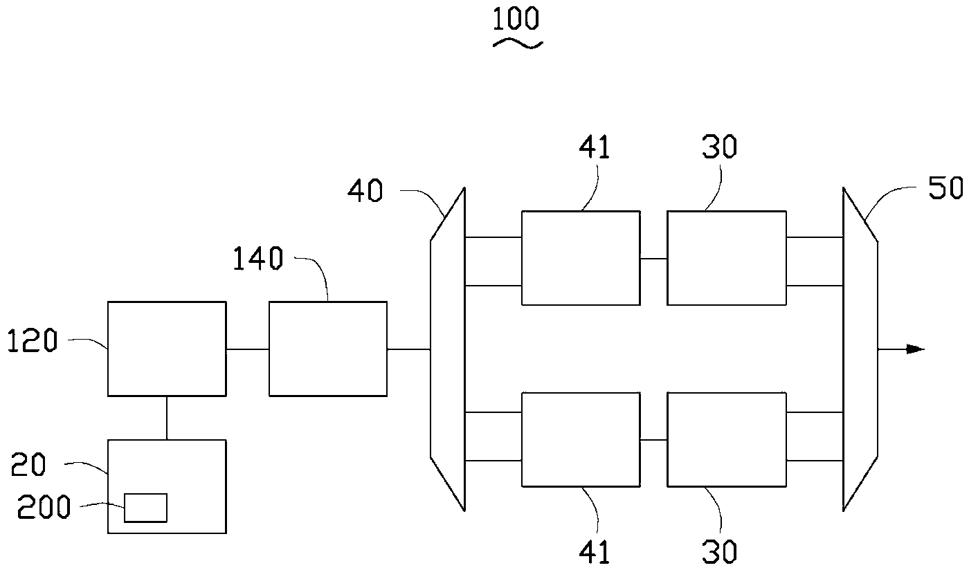
[0012] see figure 1 , the light emitting device 100 provided by the present invention includes a laser 120 and a light modulator 140 for modulating the laser light emitted by the laser 120 . The light emitting device 100 also includes a driving circuit 20 and a semiconductor optical amplifier 30 . The laser 120 is a semiconductor laser, such as a Fabry-Perot laser diode (FP LD). The light modulator 140 may be a Mach-Zehnder modulator (Mach-Zehnder Modulator).

[0013] The drive circuit 20 is connected to the laser 120, and the drive circuit 20 is added with a part that controls the drive current according to the temperature change of the laser, such as a control device, a control component, an automatic temperature control circuit, etc. to control the drive current at a lower level. value, so as to stabilize the output wavelength and avoid wavelength drift. In this embodiment, a thermistor 200 is added to the driving circuit 20 . When the ambient temperature rises, the resi...


PUM


Abstract

The invention provides a light emitting device which comprises a laser and an optical modulator which is used for modulating laser light emitted by the laser. The light emitting device further comprises a driving circuit, and the driving circuit is connected with the laser and is provided with a portion which adjusts a driving current according to the temperature change of the laser to stabilize the output wavelength of the laser.

Description

technical field [0001] The invention relates to the field of optical communication, in particular to an optical emitting device. Background technique [0002] Existing light emitting devices generally use a laser light source as the light source. However, since the laser is easily affected by temperature, as the temperature of the laser rises, the output wavelength shifts to the long wavelength direction, and the output is not stable enough. Contents of the invention [0003] In view of this, it is necessary to provide a light emitting device that is not easily affected by temperature. [0004] A light-emitting device, comprising a laser and an optical modulator for modulating the laser light emitted by the laser, the light-emitting device also includes a driving circuit, the driving circuit is connected to the laser, and the driving circuit has a function according to The part of the driving current is adjusted to stabilize the output wavelength of the laser due to the t...

Claims


Application Information

Patent Timeline
Patent Type & Authority Applications(China)
IPC IPC(8): H01S3/131H01S5/068
Inventor 萧宇超
Owner HONG FU JIN PRECISION IND (SHENZHEN) CO LTD
Learn More