Drive mechanism of automated electrically-controlled mechanical transmission

A technology of automatic transmission and drive mechanism, applied in mechanical equipment, components with teeth, transmission control and other directions, can solve the problems of motor damage, complex process, high price, etc., and achieve fast and reliable gear shifting, simple control strategy, Responsive effect

Active Publication Date: 2015-04-29
玉柴芯蓝新能源动力科技有限公司
View PDF8 Cites 0 Cited by
  • Summary
  • Abstract
  • Description
  • Claims
  • Application Information

AI Technical Summary

Problems solved by technology

[0008] 1. Two motors need to be installed, which is expensive;
[0009] 2. The motor cannot accurately control the rotation angle, so it cannot accurately control the axial displacement and rotation angle of the shift shaft;
[0010] 3. The control strategy of the controller is relatively complicated, because if you want to control the motor to stop at an accurate position and ensure a fast shift time, you have to go through the steps of starting with high torque, running at a constant speed, and reducing the torque of the motor to zero in advance, and then Reaching the exact position through the inertia of the parts, the process is more complicated, and it is difficult to guarantee the control accuracy;
[0011] 4. Because the motor is used to drive the gear pair to control the rotation of the shift shaft, and the gear shift of the transmission is also realized through the combination of the gear pair. If the top teeth of the two gears happen to appear when shifting gears, the motor will stall, which will easily cause damage to the motor.

Method used


Image

  • Drive mechanism of automated electrically-controlled mechanical transmission
  • Drive mechanism of automated electrically-controlled mechanical transmission
  • Drive mechanism of automated electrically-controlled mechanical transmission

Examples


Embodiment Construction

[0037] In order to further illustrate the structure and function of the present invention, the present invention will be described in detail below in conjunction with the accompanying drawings and preferred embodiments, but it should be understood that the protection scope of the present invention is not limited by specific embodiments.

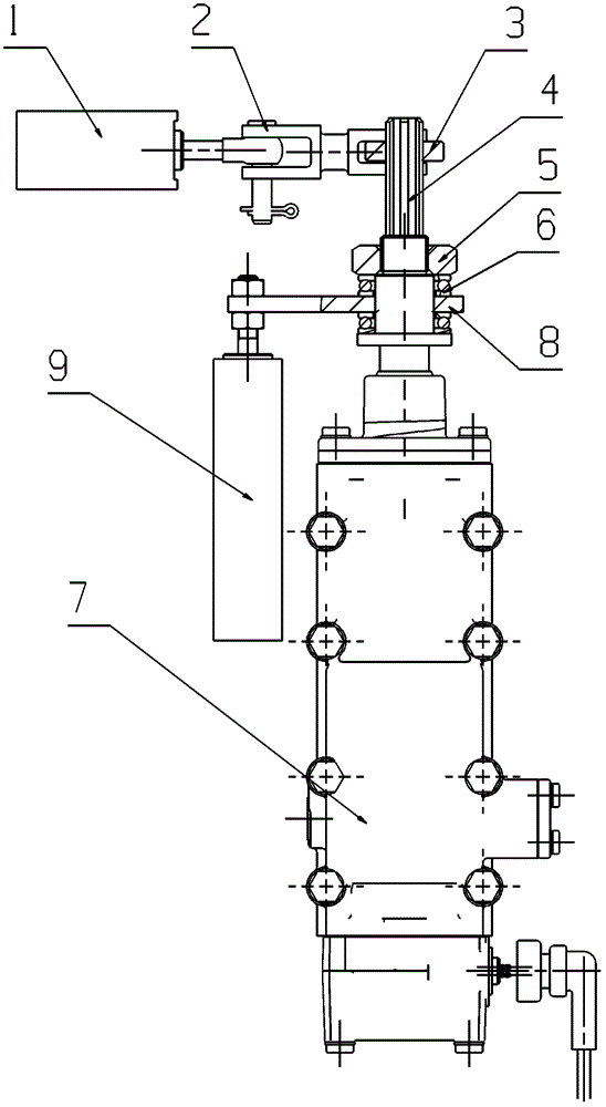
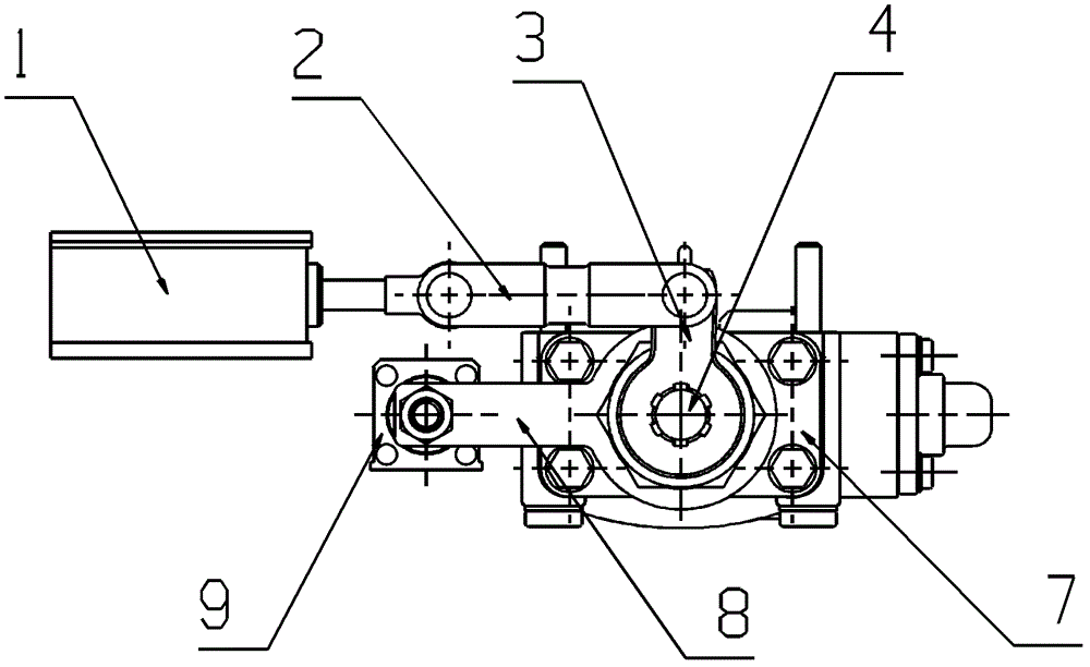
[0038] figure 1 with figure 2 They are respectively a schematic top view and a schematic rear view of the driving mechanism of the electromechanical automatic transmission of the present invention. As shown in the figure, the driving mechanism of the electromechanical automatic transmission of the present invention includes:

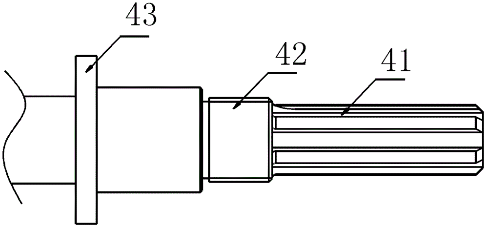
[0039] A shift shaft 4, the shift shaft 4 is a straight shaft structure, it drives the shift device in the transmission 7 through axial movement and circumferential rotation, one end of the shift shaft 4 is an inner shaft, connected to the transmission 7 , the other end is an outer shaft, which protrudes outside the t...


PUM


Abstract

The invention discloses a drive mechanism of an automated electrically-controlled mechanical transmission. The drive mechanism comprises a gear shift shaft, a gear selector air cylinder / a gear selector hydraulic cylinder, a gear selector arm, a gear shift air cylinder / a gear shift hydraulic cylinder, and a rocker arm, wherein the gear shift shaft is used for driving a gear shift device in the transmission by virtue of axial movement and circumferential rotation; a pushing rod of the gear selector air cylinder / the gear selector hydraulic cylinder is parallel to the gear shift shaft; one end of the gear selector arm can be connected to the outer shaft of the gear shift shaft in a rotary manner instead of an axially moveable manner; the other end of the gear selector arm is fixedly connected to the pushing rod of the gear selector air cylinder / the gear selector hydraulic cylinder; a pushing rod of the gear shift air cylinder / the gear shift hydraulic cylinder is vertical to the gear shift shaft; one end of the rocker arm is connected with a spline of the gear shift shaft; and the other end of the rocker arm is rotatably connected onto the pushing rod of the gear shift air cylinder / the gear shift hydraulic cylinder by a connecting rod. According to the drive mechanism of the automated electrically-controlled mechanical transmission disclosed by the invention, the air cylinder or the hydraulic cylinder is used as a gear shift power source, so that not only is the cost lower, but also the control strategy is simple, the gear shifting is quick and reliable, and the air cylinder or the hydraulic cylinder is not damaged.

Description

technical field [0001] The invention relates to the technical field of automatic transmissions, in particular to a driving mechanism for an electromechanical automatic transmission. Background technique [0002] Automated Mechanical Transmission (AMT) is referred to as AMT. The specific situation is to use the manual transmission as the mother body, and realize the automatic operation of the shift fork and shift shaft of the manual transmission. The car is the same as the automatic transmission, so that the automation of the manual transmission is realized. AMT not only has the advantages of automatic transmission of hydraulic automatic transmission, but also retains the advantages of high efficiency, low cost, simple structure and easy manufacture of the original manual transmission gear transmission. It combines the advantages of the two, and is popular with all drivers for its unique economy, convenience, safety and comfort, and has become a hot spot for development in v...

Claims


Application Information

Patent Timeline
Patent Type & Authority Patents(China)
IPC IPC(8): F16H61/28
Inventor 吴苾曜周兴利梁锋欧阳石坤谢波
Owner 玉柴芯蓝新能源动力科技有限公司
Why Eureka
Try Eureka