Pseudo-rigid-body model of flexible slider-crank mechanism

A crank-slider mechanism, pseudo-rigid body technology, applied in mechanical equipment, belts/chains/gears, transmissions, etc., can solve the problem of not considering the influence of the motion effect of the flexible rod, etc.

Inactive Publication Date: 2013-07-03
成都海翰机械设备有限公司
View PDF0 Cites 6 Cited by
  • Summary
  • Abstract
  • Description
  • Claims
  • Application Information

AI Technical Summary

Problems solved by technology

[0004] The purpose of the present invention is to provide a pseudo-rigid body model of a flexible crank-slider mechanism to solve the problem that when designing flexible elem...

Method used


Image

  • Pseudo-rigid-body model of flexible slider-crank mechanism

Examples


Embodiment Construction

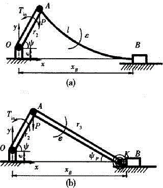
[0010] Such as figure 1 As shown, the pseudo-rigid body model of the flexible slider-crank mechanism includes a crank AO and a flexible rod AB. The crank AO can rotate in a full circle. One end of the flexible rod AB is hinged to the free end of the crank AO. The other end of the flexible rod AB passes through the characteristic Joint K is hinged with slider B.

[0011] A torsion spring is arranged inside the characteristic joint K.

[0012] The invention considers the movement of the flexible rod, and discusses the optimal design problem of the flexible crank slider mechanism with the probability assumption method of the random variable affecting the fatigue strength. The present invention is based on the pseudo-rigid body model of the flexible mechanism, which can combine the knowledge of probability, fatigue, mechanism structure, etc., and consider the influence of the dynamic effect of the mechanism movement, so as to propose an optimal design method for the flexible cran...


PUM


Abstract

The invention discloses a pseudo-rigid-body model of a flexible slider-crank mechanism, which comprises a crank and a flexible rod, wherein the crank can rotate in a complete circle; one end of the flexible pole is hinged with a free end of the crank, and the other end thereof is hinged with a sliding block through a featured joint; and a torsional spring is arranged in the featured joint. According to the invention, in consideration of motion of the flexible rod, the optimal design of the flexible slider-crank mechanism is discussed on basis of the probability hypothesis method of random variable affecting fatigue strength. Based on the pseudo-rigid-body model of the flexible mechanism, in combination with probability, fatigue, structure of mechanism and the like, and in consideration of dynamic effect influence of the mechanism motion, the invention provides an optimal design method of the flexible slider-crank mechanism.

Description

technical field [0001] The invention relates to the technical field of connectors, in particular to a flexible crank slider mechanism. Background technique [0002] Flexible mechanisms transmit motion and force through flexible deformation of flexible rods. Compared with the rigid mechanism, this mechanism has many advantages, such as: less rigid joints or no rigid joints are used between the rods, reducing the manufacturing and assembly time of the mechanism, and the overall processing characteristics and operation accuracy of the mechanism are higher. However, due to the large offset deformation of the flexible rod and the frequent reciprocating motion, it bears the action of alternating loads, which will inevitably lead to cyclical alternating stress at the flexible joints of the rod, and this stress is the influence A major factor of mechanism life and service efficiency, fatigue damage is its main failure mode. Therefore, how to design flexible elements so that they h...

Claims


Application Information

Patent Timeline
IPC IPC(8): F16H21/18F16H35/00
Inventor 赵祥均
Owner 成都海翰机械设备有限公司
Why Eureka
Try Eureka