
fuel filler cap structure

A fuel filler cap and fuel filler technology, which is applied to the layout combined with the fuel supply of internal combustion engines, power devices, transportation and packaging, etc., can solve the problems of water accumulation in the fuel filler box, exposed and rusted fuel filler pipe installation bolts, etc., and achieve Conducive to assembly, solve the effect of bolt exposure and sagging

Active Publication Date: 2016-04-27
CHERY AUTOMOBILE CO LTD
View PDF6 Cites 1 Cited by
  • Summary
  • Abstract
  • Description
  • Claims
  • Application Information

AI Technical Summary

Problems solved by technology

[0003] In the process of realizing the present invention, the inventor found that the prior art has at least the following problems: 1. The installation bolts of the fuel filler pipe are exposed; , the flatness of the gap is difficult to control; 3. Water accumulates inside the fuel filler box, causing rust; 4. Difficulty in assembly and disassembly

Method used


Image

  • fuel filler cap structure
  • fuel filler cap structure
  • fuel filler cap structure

Examples


Embodiment Construction

[0026] In order to make the object, technical solution and advantages of the present invention clearer, the implementation manner of the present invention will be further described in detail below in conjunction with the accompanying drawings.

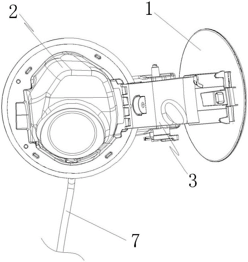
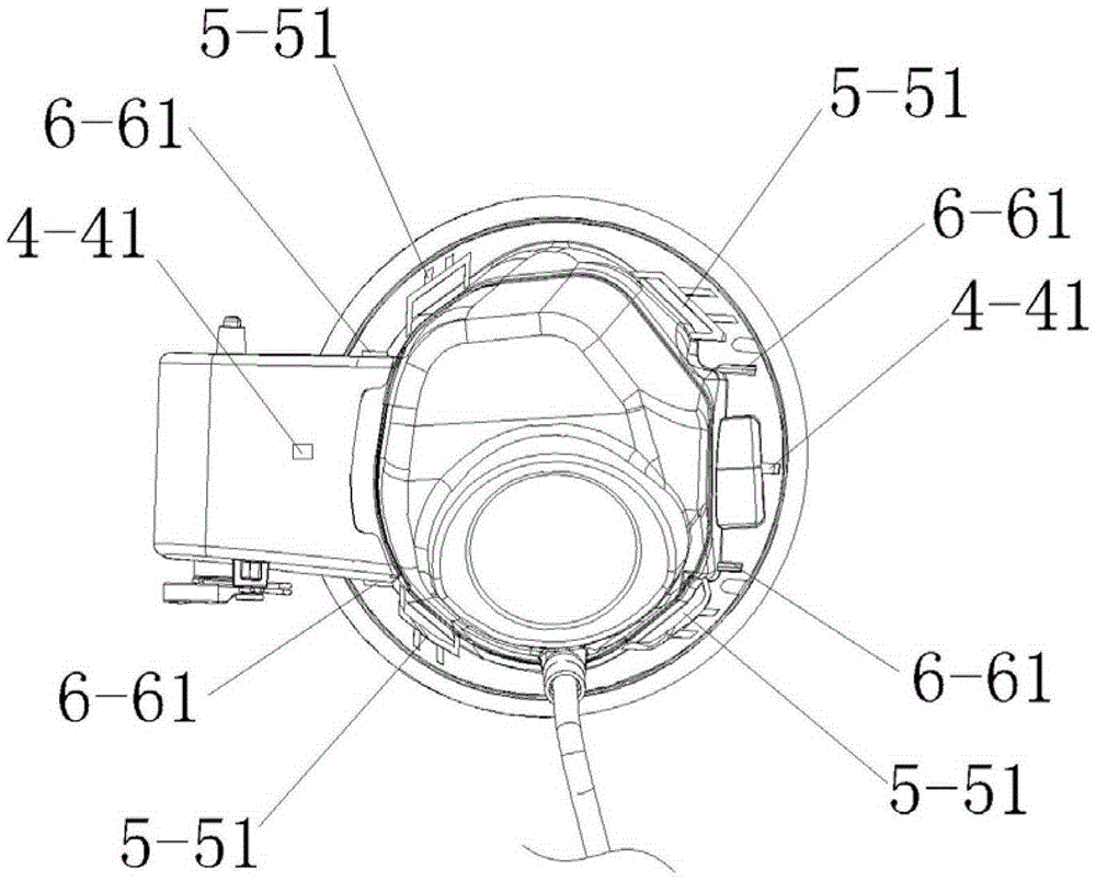
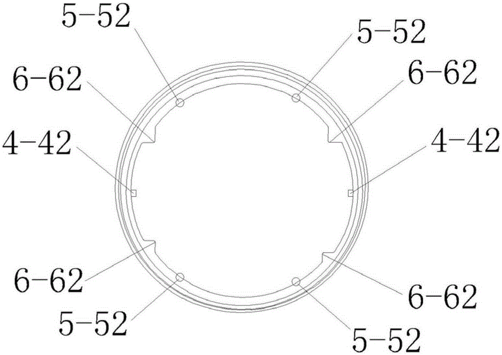
[0027] The embodiment of the present invention provides a fuel filler cap structure, please refer to Figure 1 to Figure 8 , the fuel filler cap structure includes: fuel filler cap outer plate 1, fuel filler box body 2 and fuel filler box hinge assembly 3, the fuel filler cap outer plate 1 is matched with the fuel filler box body 2, and the fuel filler box hinge The assembly 3 connects the fuel filler cap outer panel 1 and the fuel filler box body 2 . That is, the fuel filler of the automobile is arranged on the fuel filler box body 2, and the fuel filler cover outer plate 1 is used to block the fuel filler when it is not in the refueling state. The surface gap and flatness meet the design requirements, and it is beautiful and elegant...


PUM


Abstract

The invention discloses an oil filler cap structure and belongs to the field of car oil filler blocking pieces. The oil filler cap structure comprises an oil filler cap outer plate (1), an oil filler box body (2) and an oil filler box hinge assembly (3), wherein the oil filler cap outer plate (1) and the oil filler box body (2) are arranged in an adapted manner; the oil filler box hinge assembly (3) is connected with the oil filler cap outer plate (1) and the oil filler box body (2); and the oil filler cap outer plate (1) and the oil filler box body (2) are adaptively and correspondingly provided with an X-direction positioning buckle (4), a Y-direction positioning buckle (5) and a Z-direction positioning buckle (6). According to the oil filler cap structure disclosed by the invention, the X-direction positioning buckle, the Y-direction positioning buckle and the Z-direction positioning buckle are arranged, so that a buckle of the oil filler cap outer plate is clamped on a side wall outer plate and six degrees of freedom of the oil filler cap are controlled; a gap and the flatness between an oil filler cap and the side wall outer plate meet the design requirements; and the oil filler cap structure is good for assembling and can effectively solve the problem that a bolt is exposed and droops and the like.

Description

technical field [0001] The invention relates to the field of sealing parts for fuel fillers of automobiles, in particular to a fuel filler cap structure. Background technique [0002] The fuel filler cap is a component of the fuel filler installed on the side wall of the car body. It is used to meet the appearance of the fuel filler body and prevent people from being splashed by fuel. On the other hand, the fuel filler cap is also very important in the car opening and closing system. one of the components. Existing automobile filler caps include an inner cover, an outer cover and a spring leaf, wherein the outer cover and the hinge are all metal parts or a combination of metal and plastic. [0003] In the process of realizing the present invention, the inventor found that the prior art has at least the following problems: 1. The installation bolts of the fuel filler pipe are exposed; , It is difficult to control the flatness of the gap; 3. Water accumulates inside the fuel...

Claims


Application Information

Patent Timeline
Patent Type & Authority Patents(China)
IPC IPC(8): B60K15/05B60R13/07
Inventor 司爱霞胡微微曹春虎时西芳
Owner CHERY AUTOMOBILE CO LTD
Learn More