Solid phase spot welding method

A technology of solid-phase points and solder joints, applied in welding equipment, non-electric welding equipment, metal processing equipment, etc., can solve problems such as inability to fully react, weak connections, solder joints are easily torn and fail, and achieve interface connection quality Improve, improve welding efficiency, increase the effect of service life

Inactive Publication Date: 2013-07-03
SHANGHAI AEROSPACE EQUIP MFG GENERAL FACTORY
View PDF5 Cites 6 Cited by
  • Summary
  • Abstract
  • Description
  • Claims
  • Application Information

AI Technical Summary

Problems solved by technology

This method also has disadvantages, that is, when the inner collar is pressed down, there is a shearing action with the base material on the vertical interface of the outer ring. When the material backfills the space left by it, the filled material cannot fully react with the interface. weak link
This weak connection feature makes the solder joints susceptible to tearing failure

Method used


Image

  • Solid phase spot welding method
  • Solid phase spot welding method
  • Solid phase spot welding method

Examples


Embodiment Construction

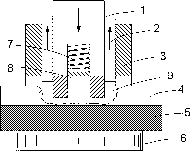
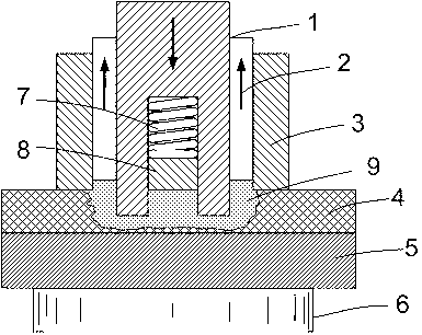
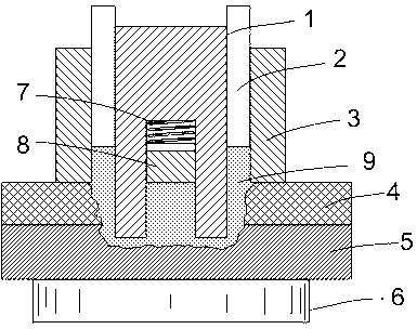
[0031] Such as Figure 1~Figure 6 As shown, the three-ring filled friction spot welding method provided by the preferred embodiment of the present invention comprises the following steps:

[0032] (1) Pressing and preheating step: the outer ring 3 is pressed against the surface of the workpiece, which provides an axial displacement reference for the welding tool and acts as a restraint material. The middle ring 2 and the inner ring 1 are pressed against the surface of the workpiece with the same Rotating at a high speed, the frictional heat generated with the base metal surface will make the surrounding metal reach a plastic softening state.

[0033] (2) Extrusion forging step: while the inner collar 1 rotates at high speed, squeeze the base metal upper plate 4 downward, and discharge the plastic metal 9 to the outside, and the middle collar 2 moves upward while maintaining high-speed rotation, for extrusion At the same time, the spring 7 above the cylindrical slider 8 in the...


PUM


Abstract

The invention discloses a solid phase spot welding method, which at least can realize the connection of two layers of lap plates. The solid phase spot welding method belongs to the technical field of welding. According to the solid phase spot welding method, a spot welding tool of three lantern rings is used for welding when the material is under the solid phase state; the inner lantern ring and the middle lantern ring rotatably rub welded materials; meanwhile, a welding point is formed by the axial movement; and the outer lantern ring performs the pressing action for holding still. During welding, the material below a sliding block is kept at the original horizontal position by the sliding block connected with a spring on the center of the inner lantern ring without generating axial direction movement, and the welding point with the flat surface is obtained after welding.

Description

technical field [0001] The invention belongs to the field of welding technology, and in particular relates to a filling type solid phase spot welding method. Background technique [0002] In the field of solid phase spot welding, there are currently two welding methods: one is the in-line friction stir spot welding method, that is, on the basis of the friction stir welding technology, the shoulder of the welding tool and the stirring are used to perform in-situ friction on the material. Stir to form a spot-welded joint. In this spot welding method, there is an exit hole for the stirring pin on the surface of the spot welding spot, that is, a keyhole, and the surface is uneven. For example, Chinese patent CN101053923A disclosed on October 17, 2007 a patent for a stirring head used in friction stir spot welding technology belongs to this technical solution. [0003] Another friction spot welding method is in-situ filling friction spot welding, which was developed by the Germ...

Claims


Application Information

Patent Timeline
IPC IPC(8): B23K20/12B23K20/26
Inventor 封小松姚君山崔凡徐奎孙耀华
Owner SHANGHAI AEROSPACE EQUIP MFG GENERAL FACTORY
Why Eureka
Try Eureka