
Novel electric control cabinet

An electrical control cabinet, a new type of technology, applied in the direction of electrical equipment shell/cabinet/drawer, electrical components, cooling/ventilation/heating renovation, etc. problems, to achieve the effect of saving energy consumption, reducing working environment requirements, and convenient application

Active Publication Date: 2013-06-26
浙江腾飞电器有限公司
View PDF4 Cites 15 Cited by
  • Summary
  • Abstract
  • Description
  • Claims
  • Application Information

AI Technical Summary

Problems solved by technology

[0003] In order to overcome the shortcomings of the existing electrical control cabinets, such as high noise, low equipment reliability, heavy daily dust removal and maintenance workload, and unsatisfactory cooling effect, the present invention provides a new type of dust-free, dry, low-noise and obvious cooling effect. Electrical control cabinet

Method used


Image

  • Novel electric control cabinet
  • Novel electric control cabinet

Examples


Embodiment Construction

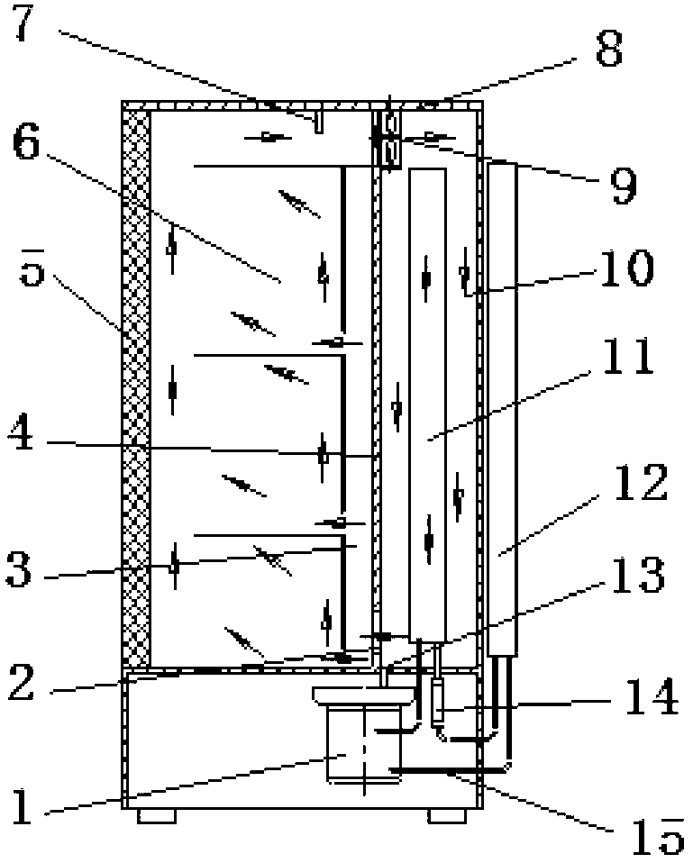
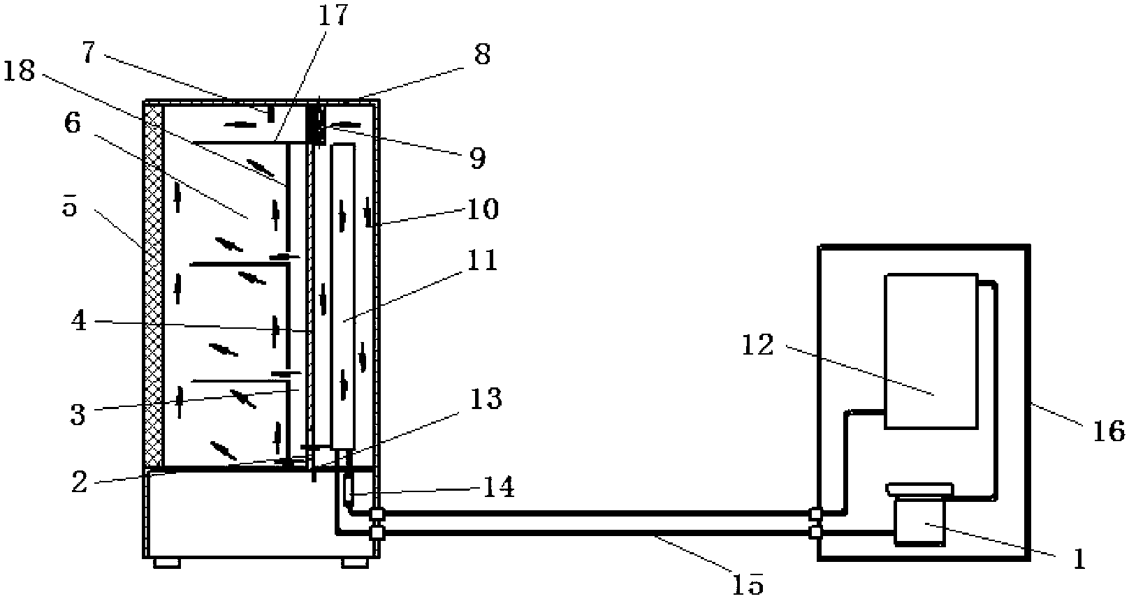
[0020] refer to figure 1 with figure 2 , a new type of electrical control cabinet, including a cabinet door 5 and a cabinet body 8, the cabinet body 8 has a closed structure, and a partition 4 is vertically provided in the cabinet body 8, and the partition board 4 separates the cabinet body 8 The internal space is divided into the equipment working area 6 and the medium cooling and drying area 10; the upper end of the partition 4 is equipped with an internal circulation fan 9, and the air flow direction flows from the equipment working area 6 to the medium cooling and drying area 10, and the bottom of the partition 4 A cold air inlet 2 is provided; a heat dissipation assembly 12 is provided on the outer wall of the cabinet body 8 close to the side of the medium cooling and drying area 10, and a heat absorbing assembly 11 is arranged in the medium cooling and drying area 10, and the heat absorbing assembly 11 is connected to the compressor 1 through the connecting pipeline 15...


PUM


Abstract

The invention discloses a novel electric control cabinet comprising a cabinet door and a cabinet body. The cabinet body is of an enclosed structure, a partition board is vertically arranged in the cabinet body, and inner space of the cabinet body is divided into an equipment working region and a medium cooling and drying region by the partition board. An inner circulating fan is mounted at the upper end of the partition board, air flows from the equipment working region to the medium cooling and drying region, and a cool air inlet is arranged below the partition board. A cooling component is arranged on the outer wall of the cabinet body close to one side of the medium cooling and drying region. A heat-absorbing component is arranged in the medium cooling and drying region. The heat-absorbing component is connected with a compressor through a connecting pipeline, the compressor is connected with the cooling component through the connecting pipeline, and the cooling component is connected with the heat-absorbing component through the pipeline. The novel electric control cabinet has the advantages of constant temperature, cleanness, dryness and low noise; and working condition requirements on the electric control cabinet are reduced, working cost for cooling apparatus and equipment is saved, and energy consumption is saved.

Description

technical field [0001] The invention relates to a novel electric appliance control cabinet. Background technique [0002] At present, the method of cooling and cooling the heating electronic components in the electrical control cabinet to improve the reliability and life of the system is to install the heating electronic components on the radiator and use ventilation to transfer the heat from the radiator to the outside of the electrical control cabinet. At the same time, air conditioners are installed in the room where the electrical control cabinet is installed to reduce the ambient temperature, so as to control the temperature rise of the heating electronic components, improve the working conditions of equipment and instruments, and increase the reliability and life of operation. Practice has proved that this method is effective, and it is also a method widely used at present. However, there are still some disadvantages in cooling equipment and instruments by means of ve...

Claims


Application Information

Patent Timeline
Patent Type & Authority Applications(China)
IPC IPC(8): H05K5/00H05K7/20
Inventor 潘玉良周斌
Owner 浙江腾飞电器有限公司
Learn More