Flow distribution device for pressurized-water nuclear reactor

A flow distribution device and nuclear reactor technology, applied in the field of pressurized water nuclear reactor flow distribution device, can solve the problems of difficult maintenance, high resistance coefficient, complex structure and installation, etc., and achieve the effect of easy maintenance and inspection, and reduce vibration

Active Publication Date: 2013-06-26
SHANGHAI NUCLEAR ENG RES & DESIGN INST CO LTD
View PDF7 Cites 9 Cited by
  • Summary
  • Abstract
  • Description
  • Claims
  • Application Information

AI Technical Summary

Problems solved by technology

[0007] Traditional flow distribution devices are mostly orifice-plate structures, which are formed by superimposing one or more layers of orifice plates with certain supports. The flow distribution effect of this structure is not ideal, and the structure and installation are relatively complicated, which is not easy to maintain, and the resistance coefficient Relatively high
[0008] The new foreign flow distribution device adopts a separate structure, which is composed of a flow distribution ring with a large number of water holes and a vortex suppression plate. The flow distribution of this structure is relatively ideal, but the flow distribution ring is welded and fixed on the pressure vessel. , maintenance is quite difficult

Method used


Image

  • Flow distribution device for pressurized-water nuclear reactor
  • Flow distribution device for pressurized-water nuclear reactor

Examples


Embodiment Construction

[0019] A pressurized water nuclear reactor flow distribution device according to the present invention will be further described below in conjunction with the accompanying drawings and specific embodiments.

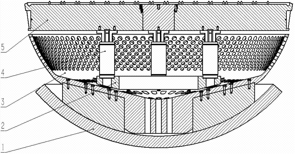
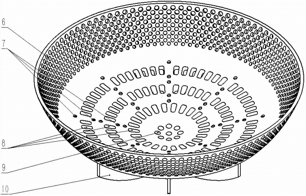
[0020] Such as figure 1 As shown, a flow distribution device for a pressurized water nuclear reactor according to the present invention has a spherical bowl-shaped mesh structure, and eight support ribs 10 are fixed below the bottom of the distribution device, and the eight support ribs 10 are fixed by connecting screws 7 Connects below the bottom of the dispensing unit.

[0021] 10 rows of circular openings are arranged rotationally symmetrically on the middle and upper part of the circumferential side wall of the bowl of the distribution device, each row of circular openings includes 100 circumferentially evenly distributed circular holes 6, and the diameters of each row of openings are different, from top to bottom The order is 66mm, 64mm, 62mm, 60mm, 58mm, 56mm, 54mm...


PUM


Abstract

The invention provides a flow distribution device for pressurized-water nuclear reactor, which is of a ball-bowl-shaped mesh structure. The flow distribution device is characterized in that the inferior of the bottom of the distribution device is fixedly provided with supporting rib plates, the middle upper part of the circumferential side wall of the ball bowl of the distribution device is provided with multiple rows of unidiameter round open pores in a rotation symmetry manner, and each row of open pores comprise a plurality of round holes which are uniformly distributed in the circumferential direction; three rows of square drain holes are formed in the positions of the lower part of the circumferential side wall of the ball bowl of the distribution device, away from a central shaft by different radial distances, each row of square drain holes comprise a plurality of square holes which are uniformly distributed in the circumferential direction, and the supporting rib plates are not provided with square holes; and the central region at the bottom of the ball bowl of the distribution device is provided with a plurality of round drain holes. The flow distribution device of the pressurized-water nuclear reactor provided by the invention can well meet the related requirements of a chamber flow field under a pressure container, the sufficient metal is filled under the serious accident working condition of a reactor core so as to meet related requirements on reactor core melting, and meanwhile, the structure has the advantages that the maintenance and the inspection are convenient, the in-pile component vibration is alleviated, and the like.

Description

technical field [0001] The invention relates to the nuclear reactor design of a pressurized water reactor nuclear power plant, in particular to a flow distribution device for a pressurized water nuclear reactor. Background technique [0002] The nuclear reactor is an important part of the nuclear steam supply system (NSSS), where the nuclear fuel maintains a controllable chain fission reaction, and the energy generated by the nuclear fission increases the temperature of the coolant flowing through the reactor, and then passes the heat energy through the coolant circulation loop derived from the core. The uniformity of reactor coolant distribution in the core will directly affect the temperature distribution of the core, and at the same time have an important impact on key safety parameters of the core such as heat pipe factor and DNBR. [0003] Before entering the core, the uniformity of the coolant is of great significance. It is related to whether the core heat can be exp...

Claims


Application Information

Patent Timeline
IPC IPC(8): G21C15/14G21C5/10
CPCY02E30/30
Inventor 林绍萱余凡丁宗华刘彬朱焜陈惠亮李源
Owner SHANGHAI NUCLEAR ENG RES & DESIGN INST CO LTD
Why Eureka
Try Eureka