
Rotating arm type axle box force measuring device and method thereof

A force-measuring device and arm-type technology, which is applied in the field of rail transit, can solve problems such as harsh limitations, and achieve the effect of reducing stress damage

Active Publication Date: 2013-06-26
CRRC QINGDAO SIFANG CO LTD
View PDF7 Cites 2 Cited by
  • Summary
  • Abstract
  • Description
  • Claims
  • Application Information

AI Technical Summary

Problems solved by technology

[0009] Another purpose of the invention is to solve the limitations of the existing test methods that are too harsh, use the simulated frame as the carrier of repeated experiments, and protect the frame, axle box and nodes accordingly, so as to reduce stress damage and control the cost of the experiment

Method used


Image

  • Rotating arm type axle box force measuring device and method thereof
  • Rotating arm type axle box force measuring device and method thereof
  • Rotating arm type axle box force measuring device and method thereof

Examples


Embodiment 1

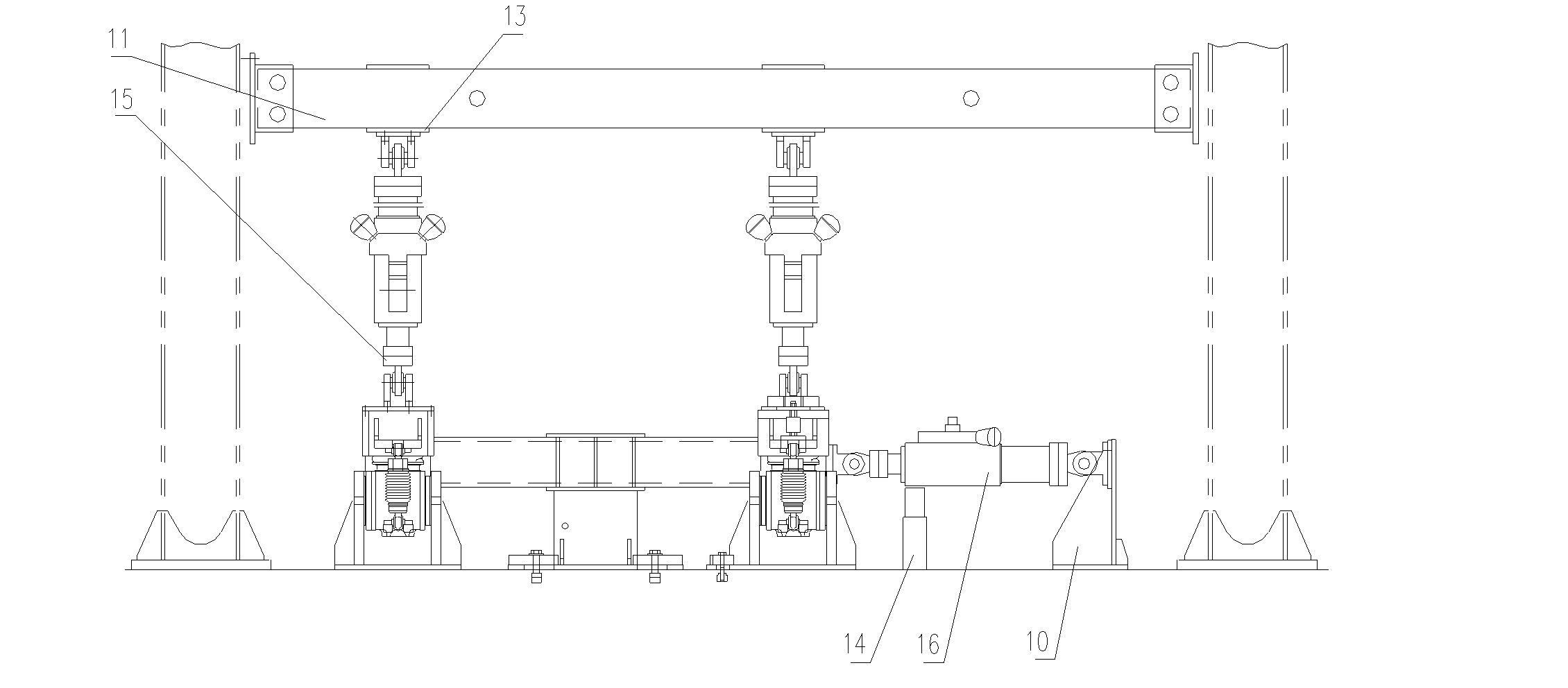
[0049] Example 1, such as Figure 1 to Figure 3 As shown, the force measuring device used to realize the method of measuring the force of the pivoting arm axle box mainly includes a loading beam 11 and a simulation frame 6, and four pivoting arm axle boxes 4 are installed according to the actual use positions.

[0050] Among them, a pair of vertical actuators 15 are connected vertically between the simulation frame 6 and the loading beam 11, that is, the bottom ends of the two vertical actuators 15 are respectively connected to the air spring seats 24 on both sides of the simulation frame 6. , the top of the vertical cylinder 15 is connected to the loading beam 11 through the cylinder hanger 13;

[0051]Connect the lateral actuator 16 to the side beam 25, and load the actuator elastic support 14 at the bottom of the lateral actuator 16;

[0052] Connect the longitudinal cylinder 17 to the center pin 26, and load the cylinder elastic support 14 at the bottom of the longitudina...


PUM


Abstract

The invention discloses a rotating arm type axle box force measuring device and a method thereof. According to distribution positions of loads exerted on rotating arm type axle boxes, the normative testing method is specified for vertical loads exerted on shock absorber bases and spring bases and vertical, transverse and longitudinal loads exerted on elastic nodes, so that actual and reliable testing parameters are provided for scientific judgment and measurement of the magnitude and directions of loads exerted on rotating arm type axle boxes. The rotating arm type axle box force measuring method comprises the steps of adopting the force measuring device comprising a loading cross beam and a simulation structure to install four rotating arm type axle boxes on the simulation structure according to actual usage positions; connecting a pair of vertical actuating cylinders between the simulation structure and the loading cross beam in the vertical direction, and connecting a transverse actuating cylinder and a longitudinal actuating cylinder respectively on horizontal side portions of the simulation structure; and connecting a first sensor between a vertical shock absorber and the simulation structure, connecting a second sensor between an axle box spring and the simulation structure, and connecting a third sensor between a node base and the simulation structure.

Description

technical field [0001] The invention relates to a device and a method for measuring multidirectional loads of a pivoting arm type axle box applied to a rail vehicle bogie, and belongs to the technical field of rail transportation. Background technique [0002] With the rapid popularization of domestic urban rail transit and the substantial increase in vehicle speed, higher design and use requirements are put forward for the bogie frame that carries the vehicle body and transmits traction. [0003] At present, the primary suspension system of the bogie used in domestic rail transit generally adopts the axle box positioning method, that is, the axle box pivot arm positioning structure, which is usually defined as the pivot arm axle box. [0004] For example, the prior patent application that discloses the following content, the application number is 201020542266.6, and the name is a series of elastic positioning devices for rail vehicles, which are arranged between the bogie f...

Claims


Application Information

Patent Timeline
IPC IPC(8): G01L5/00G01L5/16
Inventor 张洪李亚波李庆升刘为亚陈一萍张志强刘德刚王斌
Owner CRRC QINGDAO SIFANG CO LTD
Learn More