Rotary electromagnet clutch mechanism

A technology of rotating electromagnet and clutch mechanism, applied in building structure, non-mechanical transmission-operated locks, door/window accessories, etc., can solve the problems of low work efficiency, reduced safety and practical performance, high power consumption, etc. To achieve the effect of simple structure, clear division of labor, and reduction of accidents

Active Publication Date: 2015-12-09
SHENZHEN KINLONG HBS SMART TECH
View PDF5 Cites 0 Cited by
  • Summary
  • Abstract
  • Description
  • Claims
  • Application Information

AI Technical Summary

Problems solved by technology

The servo drive of the clutch mechanism mostly adopts the clutch structure of DC motor + gearbox or the clutch structure of linear electromagnet, which has low working efficiency, high power consumption, and even the possibility of knocking to unlock, and its safety and practical performance are greatly reduced.

Method used


Image

  • Rotary electromagnet clutch mechanism
  • Rotary electromagnet clutch mechanism
  • Rotary electromagnet clutch mechanism

Examples


Embodiment Construction

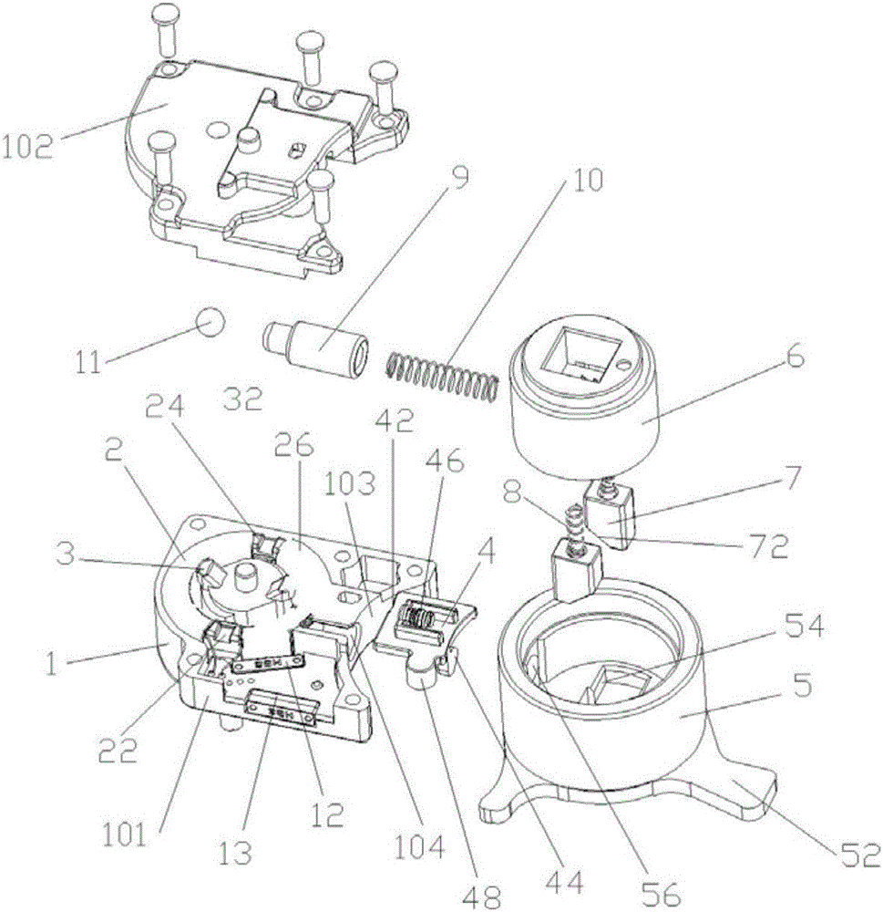
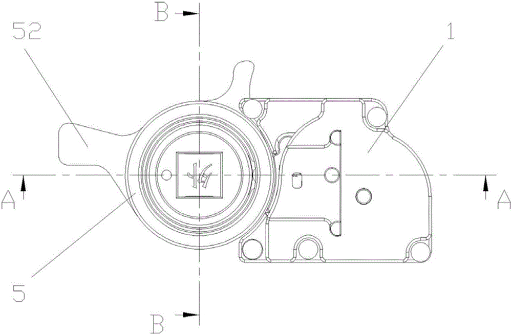
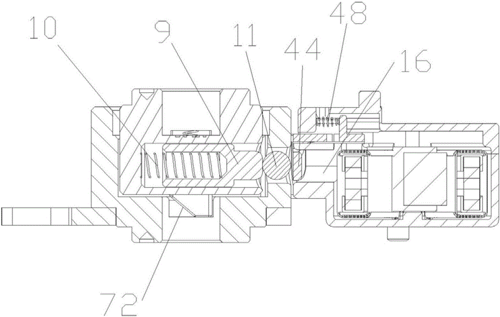
[0021] see Figure 1 to Figure 4 , the rotating electromagnet clutch mechanism, which includes a casing 1, a stator 2, a rotor 3, a clutch push plate 4, an inner handle shaft 5, an outer handle shaft 6, a clutch tooth 7, a clutch pin 9, and a steel ball 11; It is composed of a base 101 and a cover 102. The base 101 is hollow and defines a storage room with its hollow part. The stator 2, the rotor 3 and the clutch push plate 4 are installed in the storage room to form a rotating electromagnet drive servo mechanism. , The clutch pin is installed in the hole on the side of the outer handle shaft, and a spring 10 is established inside it; the steel ball is arranged between the clutch pin and the clutch push plate, and is in a free state.

[0022] The stator 2 is hollow and ring-shaped, and a through hole is formed at the center of the ring, including a stator core 22 and a winding coil 26. The stator core 22 is ring-shaped, and a diameter The clamping blocks 24 are arranged symme...


PUM


Abstract

The invention provides a rotary electromagnet type separation and reunion mechanism. The mechanism comprises a shell, a stator, a rotor, a separation and reunion push plate, an inner handle shaft, an outer handle shaft, separation and reunion teeth, a separation and reunion pin and steel balls, wherein the stator, the rotor and the separation and reunion push plate are installed in the shell; the inner handle shaft is arranged on one side of the shell, and shift rods respectively extend from the left part and the upper part of the inner handle shaft; the inner handle shaft rotates anticlockwise or clockwise; the separation and reunion teeth are installed on the outer handle shaft, and a first spring is arranged on the lower parts of the separation and reunion teeth; the outer handle shaft is installed on the inner handle shaft and coupled and linked with the separation and reunion teeth; and the separation and reunion pin is installed in a hole in the side surface of the outer handle shaft, the first spring is arranged in the separation and reunion pin, and the steel balls are arranged between the separation and reunion pin and the separation and reunion push plate. The mechanism has the beneficial technical effects that the mechanism has the characteristics of high energy conversion efficiency, good stability, smooth operation, long service life, capability of working under a lock-rotor for a long time, and the working stability of a separation and reunion drive servo system of an electronic lock can be greatly improved and service life of the separation and reunion drive servo system can be greatly prolonged.

Description

technical field [0001] The invention relates to a rotary electromagnet clutch mechanism, in particular to a clutch mechanism that can prevent 360-degree rotation from opening an anti-theft lock and is replaceable and solves the application defects of DC motors and linear electromagnet drives. Background technique [0002] As a new type of security product that has developed rapidly in recent years, electronic door locks have the advantages of high security, no metal keys, and convenient use, and have gradually become the first choice for every family to buy. However, for a long time, electronic door locks have used traditional DC motors as the driving servo components of the clutch or bolt mechanism, and the traditional DC motors have problems such as mechanical wear, arc ablation and oxidation of the commutator during work, resulting in traditional When the DC motor is used for the servo drive of the clutch and bolt mechanism of the electronic door lock, there are phenomena...

Claims


Application Information

Patent Timeline
Patent Type & Authority Patents(China)
IPC IPC(8): E05B47/06E05B3/00E05B17/20
Inventor 任克要
Owner SHENZHEN KINLONG HBS SMART TECH
Why Eureka
Try Eureka