
Solution coating machine

A coating machine and solution technology, applied in the direction of coating, liquid coating device on the surface, etc., can solve the problems of inability to meet the needs of use, low coating efficiency, small coating area, etc.

Active Publication Date: 2013-06-26
ADVANCED SOLAR POWER HANGZHOU
View PDF4 Cites 5 Cited by
  • Summary
  • Abstract
  • Description
  • Claims
  • Application Information

AI Technical Summary

Problems solved by technology

However, although the existing coating equipment has a certain isolation structure, under continuous high-intensity operations, this simple isolation protection measure cannot effectively avoid the safety hazards caused by toxic solutions to the surrounding environment and operators
At the same time, because most of the existing coating equipment adopts static nozzles, the effective coating area is small and the coating efficiency is low, which cannot meet the needs of large-area continuous spraying operations.

Method used


Image

  • Solution coating machine
  • Solution coating machine
  • Solution coating machine

Examples


Embodiment Construction

[0025] The core of the present invention is to provide a solution coating machine, the toxic solution coating operation of the solution coating machine has high safety and high coating efficiency.

[0026] In order to enable those skilled in the art to better understand the solution of the present invention, the present invention will be further described in detail below in conjunction with the accompanying drawings and specific embodiments.

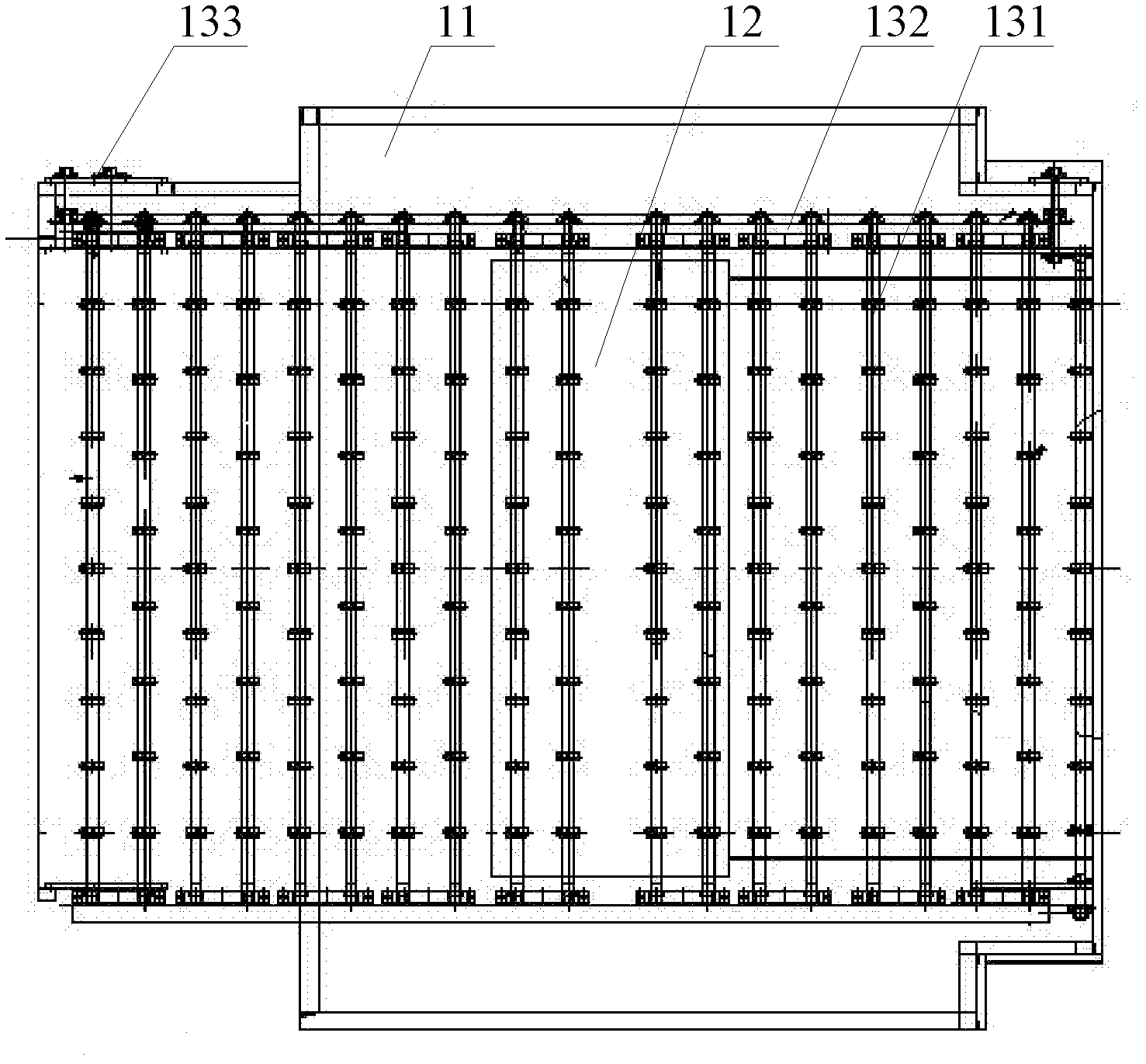
[0027] Please refer to figure 1 , figure 1 It is a schematic diagram of the assembly structure of the solution coating machine provided by a specific embodiment of the present invention.

[0028] In a specific embodiment, the solution coating machine provided by the present invention includes a frame 11, the middle part of the frame 11 is provided with an inner casing 12, and the middle part of the frame 11 is also provided with a feeding platform 13 that penetrates the inner casing 12 , the inside of the inner casing 12 is provided wi...


PUM


Abstract

The invention discloses a solution coating machine, an inner casing body is provided at the central section of a frame, a feeding platform passed through the inner casing body is provided at the central section of the frame, a nozzle is provided in the inner casing body, a reciprocating mechanism for driving the movement of the nozzle is connected to the nozzle, the movement direction of the nozzle is perpendicular to the feeding direction of the feeding platform, a waste liquid discharge port is provided at the bottom of the inner casing body, and the waste liquid discharge port is positioned at the lower part of the feeding platform; a reservoir and a transfer pump communicated with the nozzle are provided on the frame, a ultrasonic generrator cooperated with the nozzle is provided on the frame, a centrifugation blower fan used for communicating the inner casing body and an external tail gas processing apparatus is provided in the frame, a negative pressure meter is provided in the frame, a negative pressure meter measurement air tube is provided on the inner casing body, and a control module is connected to the negative pressure meter. The solution coating machine has high toxic solution coating work security and coating efficiency.

Description

technical field [0001] The invention relates to the technical field of solution spraying equipment, in particular to a solution coating machine. Background technique [0002] In the current industrial production and processing process, especially in the processing and manufacturing process of photovoltaic module products, spraying operations are usually required, that is, the industrial solution is sprayed onto the carrier of the product to be processed so that the solution is coated on the surface of the product to be processed and Form thin films or similar functional structures. [0003] At present, in the existing coating operation process, it is usually necessary to spray the toxic solution, which requires the relevant coating equipment to have certain safety protection measures to avoid the leakage of the toxic solution during the process. However, although the existing coating equipment has a certain isolation structure, under continuous high-intensity operations, th...

Claims


Application Information

Patent Timeline
IPC IPC(8): B05C5/00B05C11/00B05C11/10
Inventor 罗振
Owner ADVANCED SOLAR POWER HANGZHOU
Learn More