Voltage control light diffusion module and flashing light module and flashing light control method
A technology of voltage control and light diffusion, applied in the field of photographic equipment
- Summary
- Abstract
- Description
- Claims
- Application Information
AI Technical Summary
Problems solved by technology
Method used
Image


Examples
no. 1 example
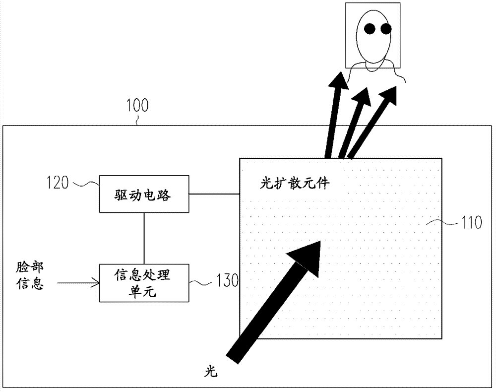
[0048] figure 1 It is a block diagram of a voltage control light diffusion module based on face information according to the first embodiment of the present invention. Please refer to figure 1 The voltage control light diffusion module 100 includes a light diffusion element 110 , a driving circuit 120 and an information processing unit 130 . Wherein, the light penetration energy of the light diffusing element 110 can be controlled by changing its driving voltage. The driving circuit 120 is coupled to the light diffusing element 110 for providing the driving voltage required by the light diffusing element 110 . The information processing unit 130 is coupled to the driving circuit 120, and the information processing unit 130 can be a physical chip or an application program in a certain physical chip to receive facial information, so as to determine the driving of the driving circuit 120 according to the facial information. The voltage changes the energy of the light source wh...
no. 2 example
[0062] Image 6 It is a block diagram of a voltage control light diffusion module based on face information according to the second embodiment of the present invention. Please refer to Image 6 , the voltage control light diffusion module 600 includes a light diffusion element 610 , a driving circuit 620 and an information processing unit 630 . The information processing unit 630 receives the face information to determine the driving voltage of the driving circuit 620 to change the energy change of the light source passing through the light diffusing element 610 .
[0063] Such as Image 6 As shown, the light diffusing element 610 includes a plurality (at least 2) of sub-blocks. Here, 6*6=36 sub-blocks are taken as an example. The driving voltage of each sub-block allows independent control, so that different sub-blocks have different degrees of light penetration. With this embodiment, the face information not only includes face size and face distance information, but als...
no. 3 example
[0068] Figure 7 is a schematic diagram of the flash control circuit according to the third embodiment of the present invention. Please refer to Figure 7 The flash control circuit 700 includes a flash light source 701 , a reflection unit 702 , a flash trigger circuit 703 and a voltage-controlled light diffusion module 704 . Wherein, the voltage control light diffusion module 704 is placed in front of the flash light source 701 , that is, it is arranged on the forward path of the light source output by the flash light source 701 (for example, the path of the straight light and the reflected light). In this embodiment, the voltage-controlled light diffusion module 704 includes a light diffusion element 710 , a driving circuit 720 and an information processing unit 730 . The functions of each component of the voltage control light diffusion module 704 of the present embodiment are the same or similar to those of the voltage control light diffusion module 100 of the first embod...
PUM
 Abstract
Description
Claims
Application Information
 - R&D
- Intellectual Property
- Life Sciences
- Materials
- Tech Scout
- Unparalleled Data Quality
- Higher Quality Content
- 60% Fewer Hallucinations
Browse by: Latest US Patents, China's latest patents, Technical Efficacy Thesaurus, Application Domain, Technology Topic, Popular Technical Reports.
© 2025 PatSnap. All rights reserved.Legal|Privacy policy|Modern Slavery Act Transparency Statement|Sitemap|About US| Contact US: help@patsnap.com