
Voltage self-adaptive control method based on insulated gate bipolar translator (IGBT) series connection loss optimization

A technology of adaptive control and series loss, applied in electrical components, electronic switches, output power conversion devices, etc., can solve the problems of increasing IGBT switching loss and reducing work efficiency, and achieve low switching loss, high reliability, and voltage. Stress controllable effect

Active Publication Date: 2013-06-19
CHINA ELECTRIC POWER RES INST +1
View PDF6 Cites 14 Cited by
  • Summary
  • Abstract
  • Description
  • Claims
  • Application Information

AI Technical Summary

Problems solved by technology

While ensuring the balance of IGBT series voltage, it will inevitably lead to the increase of IGBT switching loss, which will greatly reduce the working efficiency of high-power power electronic devices.

Method used


Image

  • Voltage self-adaptive control method based on insulated gate bipolar translator (IGBT) series connection loss optimization
  • Voltage self-adaptive control method based on insulated gate bipolar translator (IGBT) series connection loss optimization
  • Voltage self-adaptive control method based on insulated gate bipolar translator (IGBT) series connection loss optimization

Examples


Embodiment Construction

[0036] The reference voltage waveform is as figure 1 As shown, it mainly includes a pre-shutdown phase (t0-t1), a main shutdown phase (t1-t2), a pre-turn-on phase (t3-t4) and a main turn-on phase (t4-t5). The control principles of the pre-shutdown stage and the pre-open stage are the same, and the control principles of the main turn-off stage and the main turn-on stage are the same.

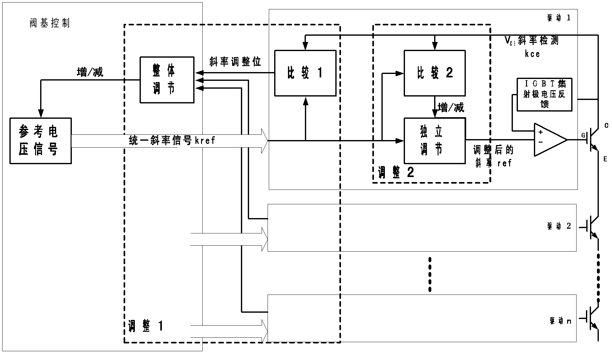
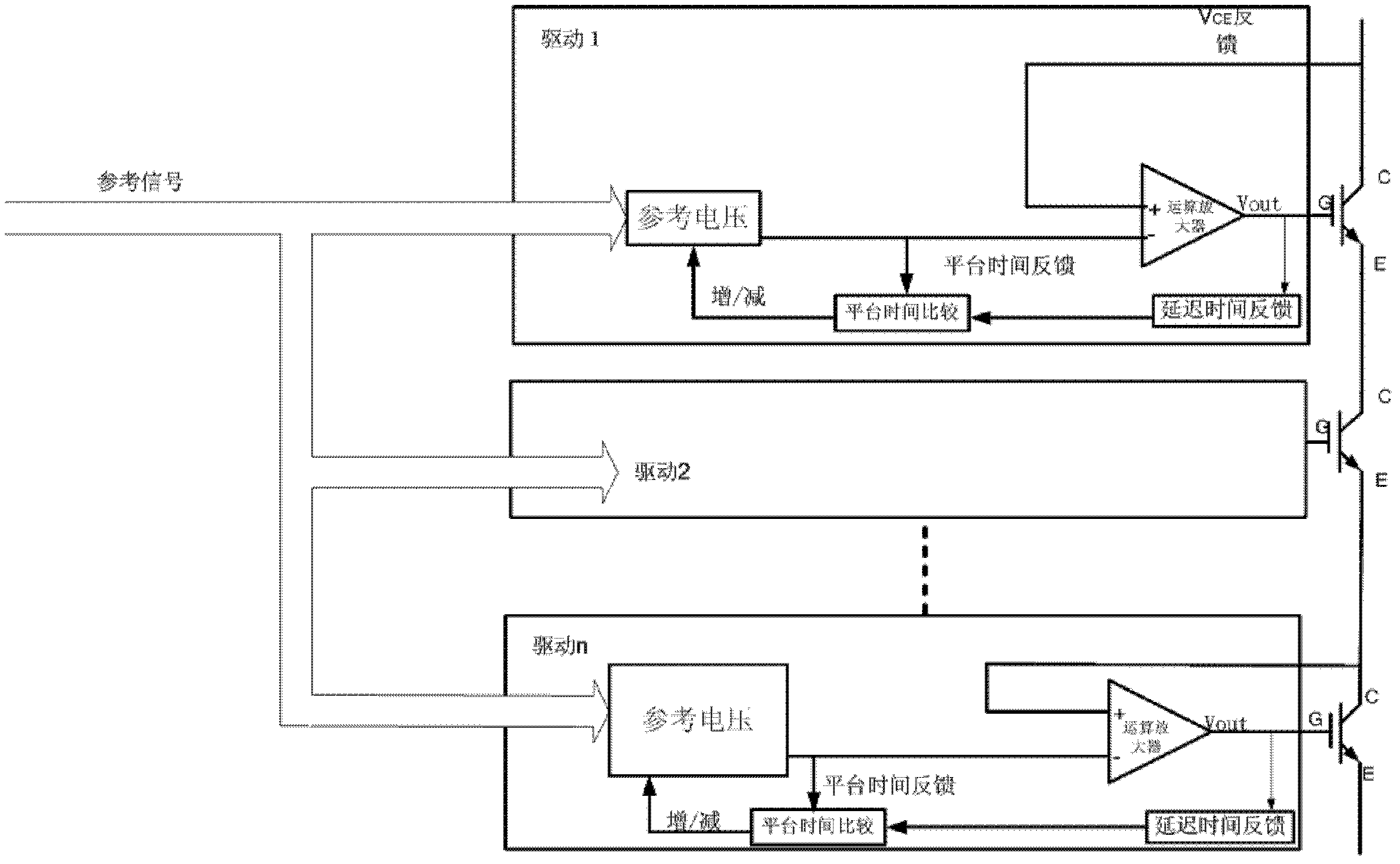
[0037] The block diagram of the main turn-off phase (t1-t2) and the main turn-on phase (t4-t5) is shown in figure 2 shown. Each IGBT is controlled by its own independent drive circuit, and the drive circuit of the IGBT on the valve arm is provided with a control signal by the same valve base control unit.

[0038] The optimal control of the main turn-off stage and the main turn-on stage is divided into two parts: adjustment 1 and adjustment 2:

[0039] Adjustment 1: Detect the IGBT terminal voltage, and compare the dv / dt when the IGBT switches with the reference voltage dv / dt delivered by the...


PUM


Abstract

The invention provides a voltage self-adaptive control method based on insulated gate bipolar translator (IGBT) series connection loss optimization. The method comprises the following steps: (1) detecting voltage of the IGBT end; (2) adjusting master switch stage time; and (3) adjusting pre-switch stage time. The voltage self-adaptive control method has the advantages that voltage balance reliability is high in the process and switching loss is low when IGBTs are connected in series, and voltage stress of an IGBT switch is controllable.

Description

technical field [0001] The invention relates to the field of electronic power systems. Specifically, it relates to a voltage adaptive control method based on IGBT series loss optimization voltage. Background technique [0002] The semiconductor power switching device that appeared in the mid-1980s - the insulated gate bipolar power transistor IGBT (Insulated Gate Biploar Transistor) is a composite device, its input control part is a MOSFET, and the output stage is a bipolar junction transistor. It has the advantages of both MOSFET and power transistor: high input impedance, voltage control, low driving power, fast switching speed, operating frequency up to 10-40kHz, low saturation voltage, large voltage and current capacity, and wide safe working area. However, the disadvantage of IGBT is that the voltage and current allowable value of a single IGBT are difficult to increase. In order to apply to high-voltage and high-power fields, the method of connecting IGBTs in series i...

Claims


Application Information

Patent Timeline
Patent Type & Authority Applications(China)
IPC IPC(8): H02M1/08
CPCH03K17/107H02M1/088
Inventor 温家良、陈中圆、韩健、吴锐、蔚泉清、贾娜、庞宇刚
Owner CHINA ELECTRIC POWER RES INST
Learn More