Microscope machine platform structure

A technology for microscopes and worktables, which is applied in optics, instruments, projection devices, etc., can solve problems such as wafer collisions, microscope defects, and damaged wafers, and achieve cost savings, simple structure, and avoid potential safety hazards.

Inactive Publication Date: 2013-06-19
CSMC TECH FAB2 CO LTD
View PDF6 Cites 1 Cited by
  • Summary
  • Abstract
  • Description
  • Claims
  • Application Information

AI Technical Summary

Problems solved by technology

[0007] However, the sensor of this structure only works when the wafer box is installed. During the working process of the microscope, if the wafer box is taken away artificially, the sensor will not send any alarm signal. This problem is a defect of the microscope software.
After the wafer cassette is taken away, there is no wafer cassette on the working table. The operator will put a new wafer cassette after finding it. However, the wafer in the previous wafer cassette is being held by the robot for inspection. After the detection, the manipulator will put it back into the wafer cassette, but it is already a new wafer cassette at this time, and this wafer cassette has no space for the wafers of the previous wafer cassette to be placed, and it will happen after the robot places it forcibly. The imagination of wafers colliding with each other not only damages the wafers, but also poses certain safety hazards

Method used


Image

  • Microscope machine platform structure
  • Microscope machine platform structure
  • Microscope machine platform structure

Examples


Embodiment Construction

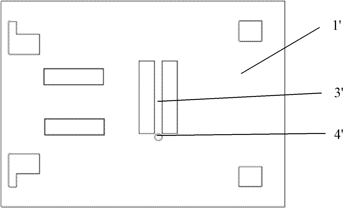
[0027] see figure 1 As shown, a microscope machine structure in the prior art is used to inspect wafers. The microscope is equipped with a robot arm for grabbing the wafer. Several wafers are accommodated in a wafer box. The wafer box is fixed on the microscope machine structure. The structure of the microscope machine includes a worktable 1' that can move up and down and a drive motor that drives the worktable 1' to move up and down. The worktable 1' is provided with a slot 3' for positioning the wafer cassette and a sensor 4' for sensing whether the wafer cassette is installed on the worktable 1'.

[0028] The working principle of the microscope machine structure in the prior art is: during normal testing, when the wafer cassette with the wafer installed is correctly clamped into the slot 3', the sensor 4' senses that the wafer cassette has been correctly installed in the slot 3'. On the working table 1', an induction signal will be sent out to indicate that the equipmen...


PUM


Abstract

A microscope machine platform structure is used for placing wafers. A plurality of wafers are contained in a wafer box. The microscope machine platform structure comprises a work platform surface which can move up and down and a drive motor which can control the work platform surface to move up and down. A clamping groove for clamping the wafer box and a sensor which is used for sensing whether the wafer box is mounted on the work platform surface or not are arranged on the work platform surface. The microscope machine platform structure further comprises a fixing lock for locking the wafer box and the fixing lock rotate with the rotation of the drive motor. Due to the fact that the fixing lock is arranged to lock the wafer box, the fact that someone takes the wafer box from the work platform surface by mistake in the working process of a microscope can be prevented, and the fact that the wafers are damaged and other safety hidden dangers occur can be avoided.

Description

technical field [0001] The invention relates to the field of wafer manufacturing, in particular to a microscope machine structure for semiconductor detection. Background technique [0002] A microscope is an optical instrument composed of one or more sets of lenses, and it is a sign that human beings have entered the atomic age. A microscope is an instrument used to magnify tiny objects so that they can be seen by the human naked eye after magnification. Microscopes can be classified into optical microscopes and electron microscopes according to their microscopic principles. [0003] An optical microscope usually consists of an optical part, an illumination part and a mechanical part. There is no doubt that the optical part is the most critical, it consists of eyepiece and objective lens. At present, there are many types of optical microscopes, mainly bright field microscopes (ordinary optical microscopes), dark field microscopes, fluorescence microscopes, phase contrast ...

Claims


Application Information

Patent Timeline
IPC IPC(8): G03B21/26G03B21/00
Inventor 陆琦
Owner CSMC TECH FAB2 CO LTD
Why Eureka
Try Eureka