Air flue well used for wind tower power generation station

A technology for wind tower power stations and air ducts, applied in wind power generation, wind power generator components, wind power engines, etc., can solve problems such as single structure of hot air flow channels, difficulty in forming sufficient upward thrust, and difficulty

Active Publication Date: 2015-03-04
周登荣 +1
View PDF6 Cites 0 Cited by
  • Summary
  • Abstract
  • Description
  • Claims
  • Application Information

AI Technical Summary

Problems solved by technology

The structure of the hot air flow channel is single, and it is difficult for the air to form enough upward thrust in this kind of hot air flow channel to push the worm wheel to rotate, and then it is difficult to drive the generator on the worm wheel shaft to rotate to generate electricity

Method used


Image

  • Air flue well used for wind tower power generation station
  • Air flue well used for wind tower power generation station
  • Air flue well used for wind tower power generation station

Examples


Embodiment 1

[0033] The best preferred embodiment 1: an air duct shaft for a wind tower power station

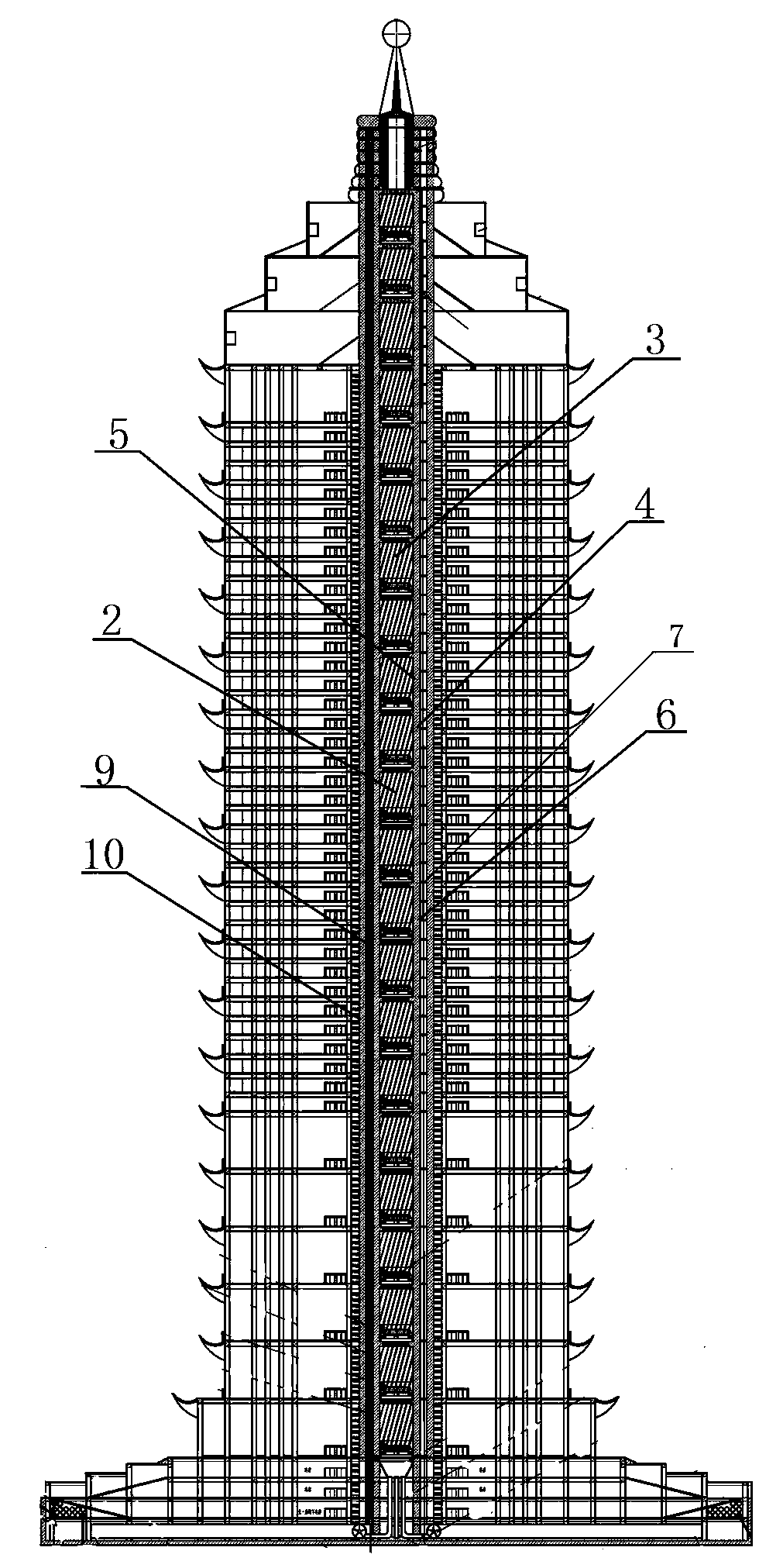
[0034] figure 1 It is a schematic architectural diagram of the blade cylinder wall installed with the wind duct well structure of the wind tower power station of the present invention. It includes stationary blades 2, running rails 3, blade cylinder walls 4, duct well outer wall pipes 7, air duct well inner walls 9, air duct well outer walls 10, cylinder wall outer walls 6, and cylinder wall inner walls 5. The running track 3 is formed between the stationary blades 2 , the inner wall 9 of the air duct well is fixedly connected with the outer wall 6 of the tube wall 6 through the outer wall pipe 7 of the air duct well, and the outer wall pipe 7 of the air duct well is arranged around the inner wall 10 of the air duct well.

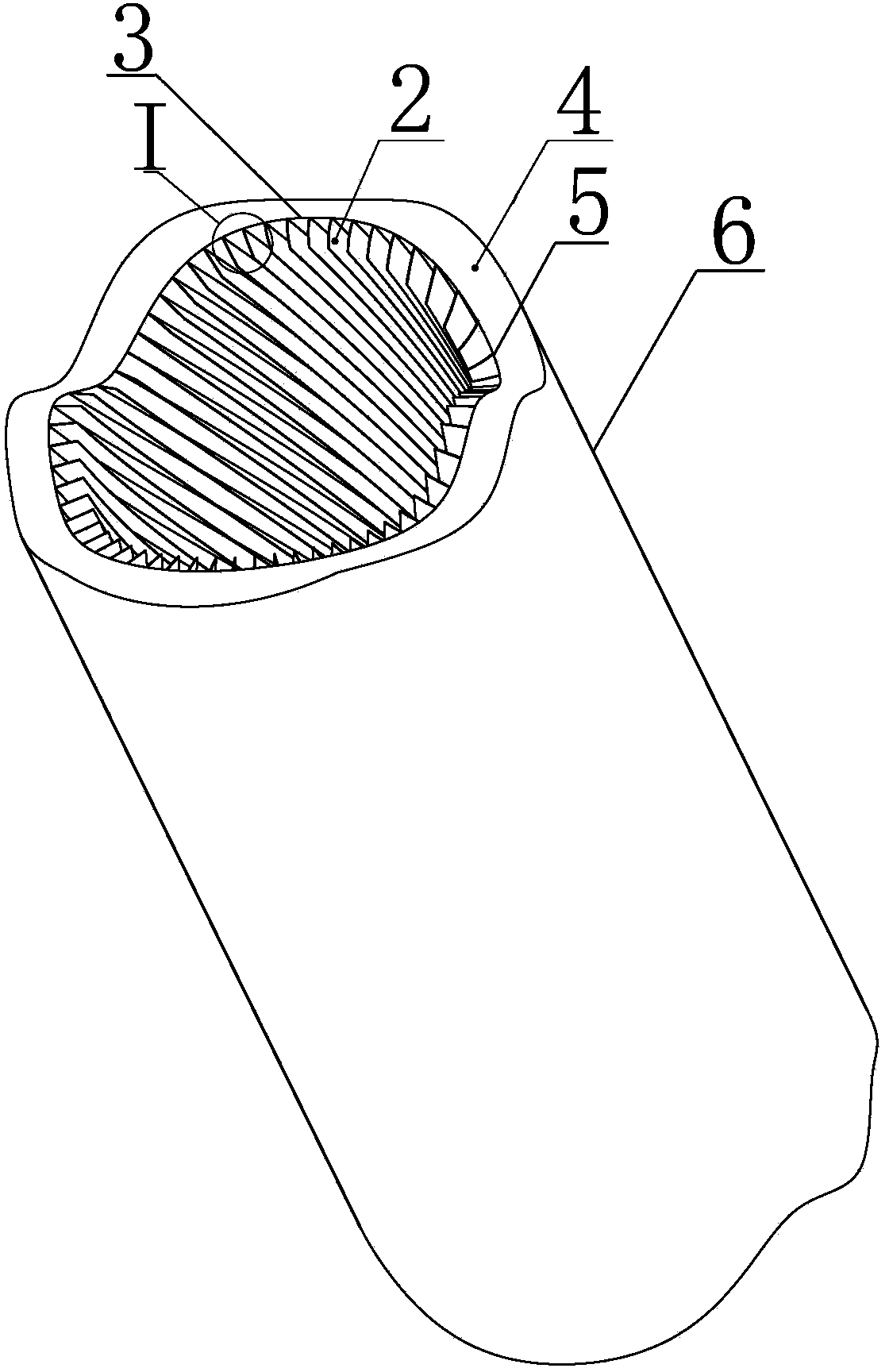
[0035] figure 2 A three-dimensional structure diagram of an air duct shaft for a wind tower power station according to the present invention is shown, which ...


PUM


Abstract

The invention relates to an air flue well used for a wind tower power generation station. The air flue well used for the wind tower power generation station comprises a cylinder wall (4), an air flue well outer wall pipeline (7), static blades (2) and operational rails (3) formed among the static blades (2). The air flue well used for the wind tower power generation station has the advantages of being simple in manufacture, reasonable in structure, low in cost, wide in use and the like.

Description

technical field [0001] The invention relates to an air duct well used in a wind tower power station, in particular to a power generation tower wall structure used for generating electricity in the air duct well. Background technique [0002] At present, most of the pipes are old-fashioned structures, and their application fields are single. In some special occasions, such as old-fashioned pipes in air duct shafts, it is difficult to apply. [0003] For example, the patent application No. 02154453.0 discloses a building exhaust pipe, which includes an airway wall and an airway, and is characterized in that there is at least one thin strip in the airway wall. Since the thin strips are set in the airway wall, the strength and rigidity of the airway wall are greatly improved, and the wall thickness of the airway wall can be reduced accordingly, material consumption can be reduced, the weight of the exhaust pipe can be reduced, and the cost can be reduced. It is easy to carry ...

Claims


Application Information

Patent Timeline
Patent Type & Authority Patents(China)
IPC IPC(8): F03D9/00F03D11/00
CPCY02E10/722Y02E10/72Y02P70/50
Inventor 周登荣周剑
Owner 周登荣
Why Eureka
Try Eureka