
Communication equipment room and air flue regulation method thereof

A communication equipment room and air duct technology, applied in the field of communication, can solve the problems of increased air-conditioning volume and low refrigeration utilization efficiency, and achieve the effect of uniform air pressure

Active Publication Date: 2013-06-19
HUAWEI DIGITAL POWER TECH CO LTD
View PDF6 Cites 4 Cited by
  • Summary
  • Abstract
  • Description
  • Claims
  • Application Information

AI Technical Summary

Problems solved by technology

In this design scheme, there is an obvious overdesign in the size design of the air duct space in the early communication room, which makes the consumption of air-conditioning cooling air significantly increased to achieve the same heat dissipation effect, resulting in low cooling utilization efficiency
[0006] In addition, due to the randomness and unpredictability of the business development of the communication equipment room, the phased deployment and gradual expansion of the communication equipment room often exist

Method used


Image

  • Communication equipment room and air flue regulation method thereof
  • Communication equipment room and air flue regulation method thereof
  • Communication equipment room and air flue regulation method thereof

Examples


Embodiment Construction

[0033] In order to make the purpose, technical solutions and advantages of the embodiments of the present invention clearer, the technical solutions in the embodiments of the present invention will be clearly and completely described below in conjunction with the drawings in the embodiments of the present invention. Obviously, the described embodiments It is a part of embodiments of the present invention, but not all embodiments. Based on the embodiments of the present invention, all other embodiments obtained by persons of ordinary skill in the art without making creative efforts belong to the protection scope of the present invention.

[0034] The serial numbers of the following embodiments of the present invention are for description only, and do not represent the advantages and disadvantages of the embodiments.

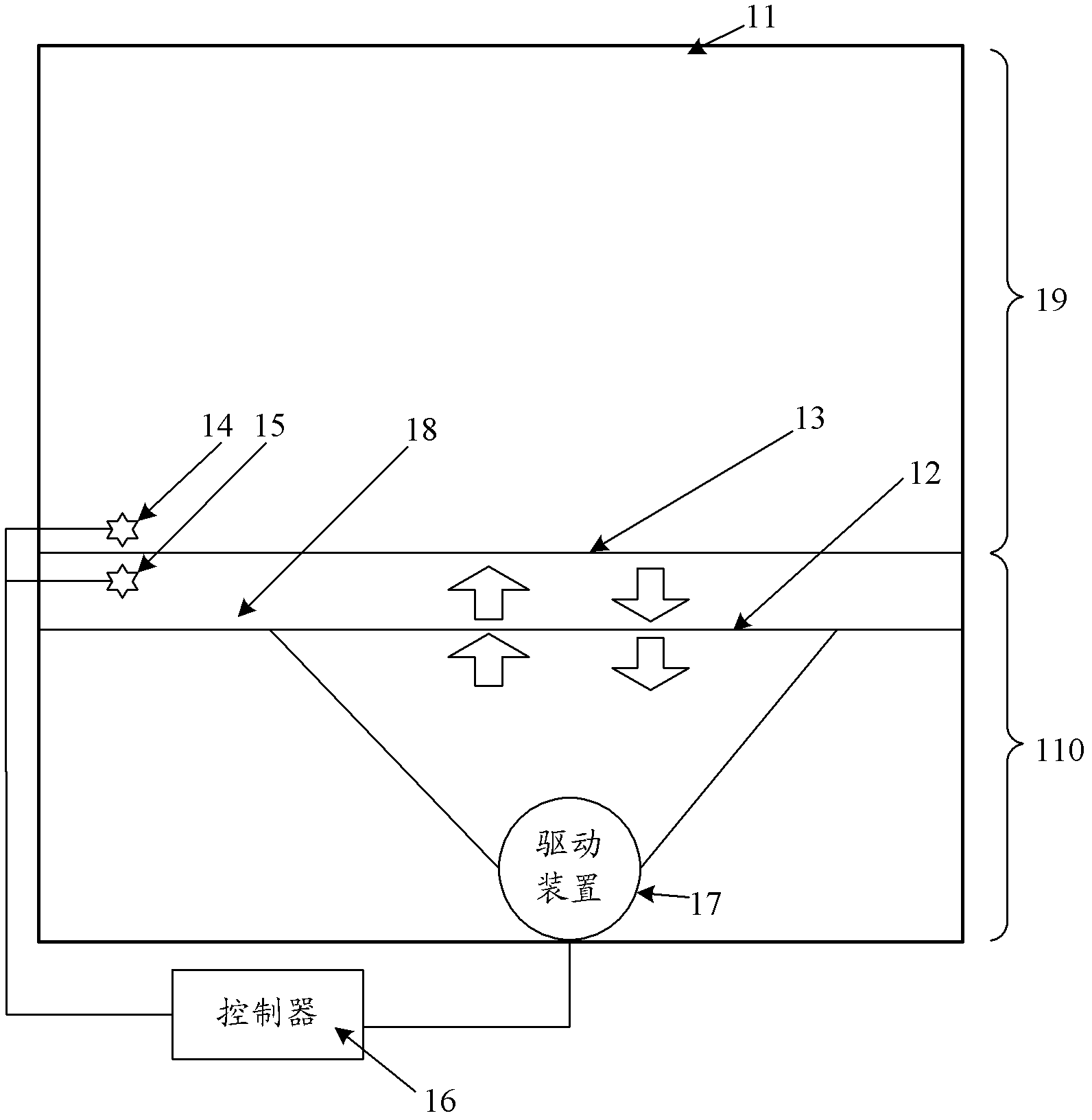
[0035] figure 1 It is a schematic structural diagram of the communication equipment room provided by Embodiment 1 of the present invention. In this embodiment, ...


PUM


Abstract

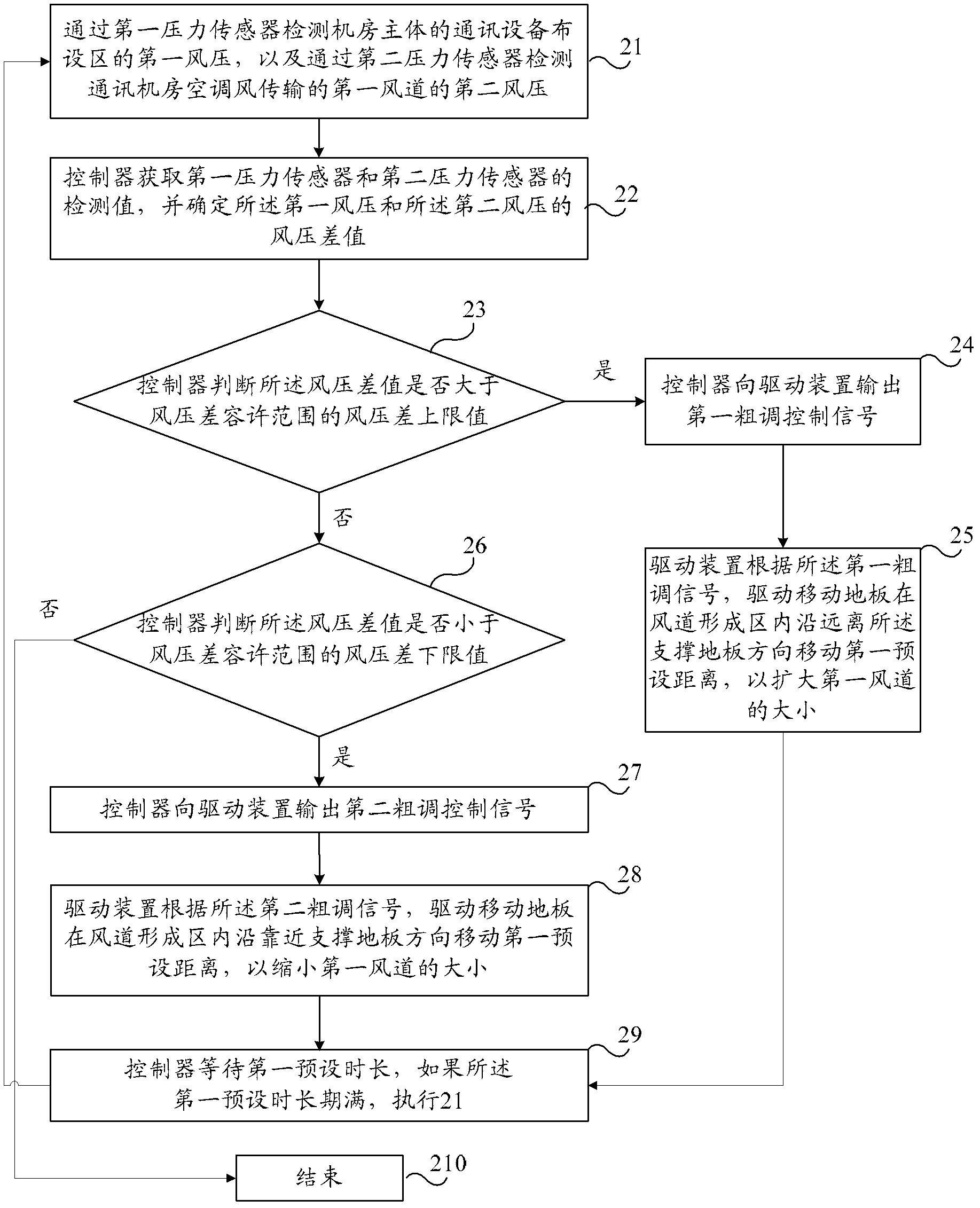
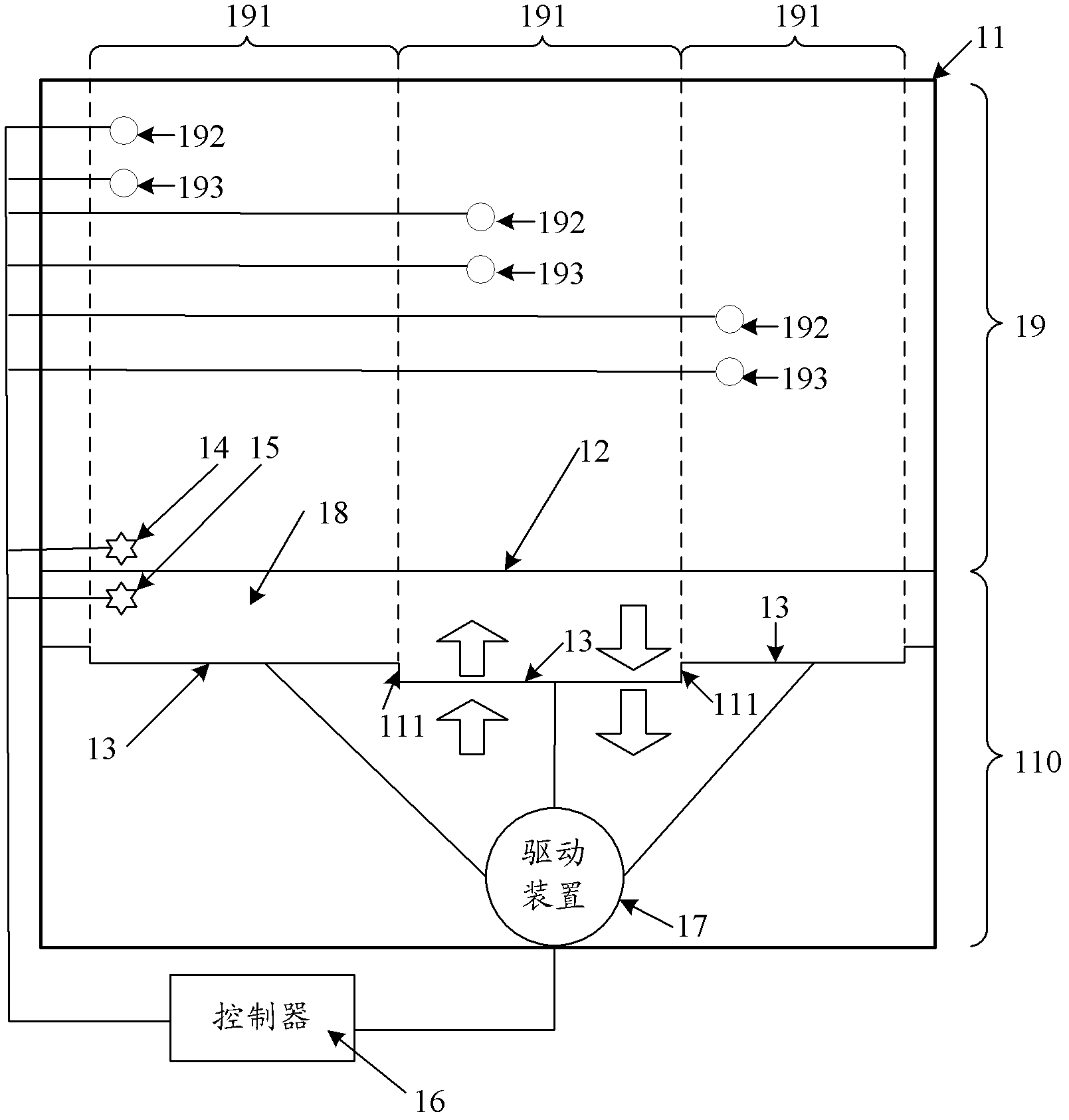
The invention discloses a communication equipment room and an air flue regulation method thereof. The communication equipment room comprises an equipment room body, a supporting plate which divides the equipment room body vertically into a communication equipment arrangement area and an air flue forming area, a mobile plate which is located in the air flue forming area, an air flue, a first pressure sensor which is arranged in the communication equipment arrangement area and used for detecting first wind pressure in the communication equipment arrangement area, a second pressure sensor which is arranged in the air flue and used for detecting second wind pressure in the air flue, a controller which is respectively connected with the first pressure sensor and the second pressure sensor and used for ascertaining a wind pressure difference value and outputting a first control signal, and a driving device which is respectively connected with the mobile plate and the controller and used for driving the mobile plate to move in the air flue forming area according to the first control signal, wherein the area between the mobile plate and the supporting plate is the air flue and air conditioner wind of the communication equipment room is transmitted through the air flue. According to the communication equipment room and the air flue regulation method thereof, the size of the air flue of the communication equipment room can be regulated, so that the heat radiation effect of the communication equipment room can be improved at a low cost.

Description

technical field [0001] The embodiments of the present invention relate to the technical field of communication, and in particular to a communication machine room and an air duct adjustment method thereof. Background technique [0002] The communication equipment room often adopts the form of raising the floor to form an air supply duct or increasing the ceiling space to form a return air duct, etc., to reduce the mixing of hot and cold air in the communication equipment room, thereby improving the efficiency of air conditioning and cooling, and saving its operating energy consumption. [0003] In the prior art, the space size of the air supply duct and the return air duct of the communication machine room is fixed. With the increase of equipment business capabilities, the power consumption density of equipment is also increasing. In order to ensure the normal heat dissipation requirements of the communication equipment room, there are often two choices in the design and cons...

Claims


Application Information

Patent Timeline
Patent Type & Authority Applications(China)
IPC IPC(8): E04H5/02E04F17/04F24F11/02
Inventor 黄文雄王大伟
Owner HUAWEI DIGITAL POWER TECH CO LTD
Learn More