
Snow clearing bucket side plates of snowplow and snowplow

A technology for snow blowers and snow buckets, used in snow surface cleaning, cleaning methods, construction, etc., can solve problems such as large resistance and easy blockage of snow, and achieve the effects of improving efficiency, reducing propulsion resistance, and preventing side plate deformation.

Inactive Publication Date: 2013-06-19
SHANDONG TIEHUA IND
View PDF11 Cites 1 Cited by
  • Summary
  • Abstract
  • Description
  • Claims
  • Application Information

AI Technical Summary

Problems solved by technology

[0003] The invention provides a side plate of a snow blower and a snow blower of a snow blower, which can solve the problem of large resistance and easy blockage of snow in the prior art

Method used


Image

  • Snow clearing bucket side plates of snowplow and snowplow
  • Snow clearing bucket side plates of snowplow and snowplow
  • Snow clearing bucket side plates of snowplow and snowplow

Examples


Embodiment 1

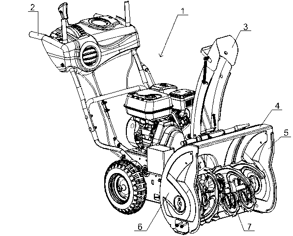
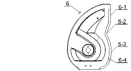
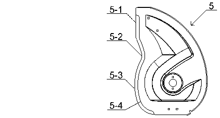
[0028] see figure 1 , the snow blower 1 includes a handle 2, a snow lift mouth 3 and a snow bucket 4, the two sides of the snow bucket 4 are the left snow bucket side plate 5, the right snow bucket side plate 6, and the snow bucket 4 is provided with a stirring cage7.

[0029] see figure 1 , figure 2 and image 3 , in order to make the side plates of the snow clearing bucket gradually cut into the snow layer when clearing snow, so as to reduce the propulsion resistance, the design concept of the present invention is to form a forward edge on the front edges of the left and right snow bucket side plates 5,6. Protruding arc segments 5-3, 6-3, the section of the protruding arc segments 5-3, 6-3 is from the middle upper part to the lower part. Since the protruding arc sections 5-3 and 6-3 do not contact the snow layer at the same time, but gradually cut into the snow layer, the resistance is reduced and the snow-clearing effect is improved.

[0030] As far as the speci...

Embodiment 2

[0035] Different from Embodiment 1, there is no concave section, and the front edges of the left and right snow bucket side plates 5, 6 form a straight line section and a protruding arc section sequentially from top to bottom. The protruding arc occupies about 60% of the area, that is, extending from the upper middle part of the side panel to the lower part.

Embodiment 3

[0037] Change the straight line section of embodiment 1 into a protruding arc segment, and the protruding high point of the protruding arc segment is slightly smaller than the protruding arc segment, namely forming a small protruding arc segment. That is, the front edges of the left and right snow bucket side plates 5, 6 form a small convex arc section, an inner concave section and a convex arc section sequentially from top to bottom.


PUM


Abstract

The invention provides snow clearing bucket side plates of a snowplow and the snowplow. The problems of large resistance and easily accumulated snow blocking in the prior art can be solved. The technical scheme is that the snow clearing bucket side plates of the snowplow comprises a left snow clearing bucket side plate and a right snow clearing bucket side plate, and protruding arc sections are at least formed by one portion of the front edge of the left snow clearing bucket side plate and one portion of the front edge of the right snow clearing bucket side plate. The lower middle portion of the front edge of the left snow clearing bucket side plate and the lower middle portion of the front edge of the right snow clearing bucket side plate are designed to be provided with the protruding arc sections, each arc section is in an arc shape with two sides low and the middle high and is in a broad axe shape, forward protruding high points of the arc sections firstly make contact with snow ice, and the other sections of the arc sections gradually cut in the snow ice when accumulated snow is removed just like the fact that the side edge in the broad axe shape gradually hacks into frozen snow cover. The snow clearing bucket side plates of the snowplow and the snowplow have the advantages that forward pushing resistance is little, time and labor are saved, and efficiency is improved due to the fact that the side plates do not simultaneously make contact with the snow cover but gradually cut into the snow cover.

Description

technical field [0001] The invention belongs to equipment for clearing snow, in particular, relates to an improvement of a side plate of a snow clearing bucket of a snow blower, and the improved snow blower. Background technique [0002] The front end of the snow plow is equipped with a snow clearing bucket, and a stirring cage is arranged in the snow clearing bucket. When clearing snow, through the rotation of the stirring cage, the snow is collected into the snow bucket, and then the snow is transported to the snow lift mouth by the snow bucket, and finally thrown out from the snow lift mouth, so as to achieve the purpose of snow removal. The front edge of the snow bucket side plate of the prior art snow blower is linear from top to bottom, and there are following deficiencies according to user feedback: 1. When encountering frozen snow or a hard snow layer that is frozen on the surface, due to The edge of the side plate of the snow clearing bucket is straight, and the si...

Claims


Application Information

Patent Timeline
IPC IPC(8): E01H5/06
Inventor 周玉亮
Owner SHANDONG TIEHUA IND
Learn More