Welding machine

A technology for welding machines and welding parts, which is applied in welding equipment, auxiliary welding equipment, welding/cutting auxiliary equipment, etc. It can solve the problems of time-consuming cleaning, hot welding head, easy to be stained with dirt, etc., and achieve the effect of prolonging the service life

Inactive Publication Date: 2013-06-19
SIP GOLDWAY TECH
View PDF8 Cites 5 Cited by
  • Summary
  • Abstract
  • Description
  • Claims
  • Application Information

AI Technical Summary

Problems solved by technology

The current welding machine generally includes a bracket, a base set in the bracket, a welding piece clamping device fixed on the base for clamping the welding piece, and a welding head for the welding piece. The welding head is easy to be stained after a long time of use. Dirt will affect the use of the welding head. At present, in terms of cleaning the welding head, manual cleaning is generally used. Although manual cleaning can be cleaned, the welding head is generally very hot after welding and is easy to burn. If it is very difficult to clean after the welding head cools down, cleaning is very time-consuming

Method used


Image

  • Welding machine
  • Welding machine
  • Welding machine

Examples


Embodiment Construction

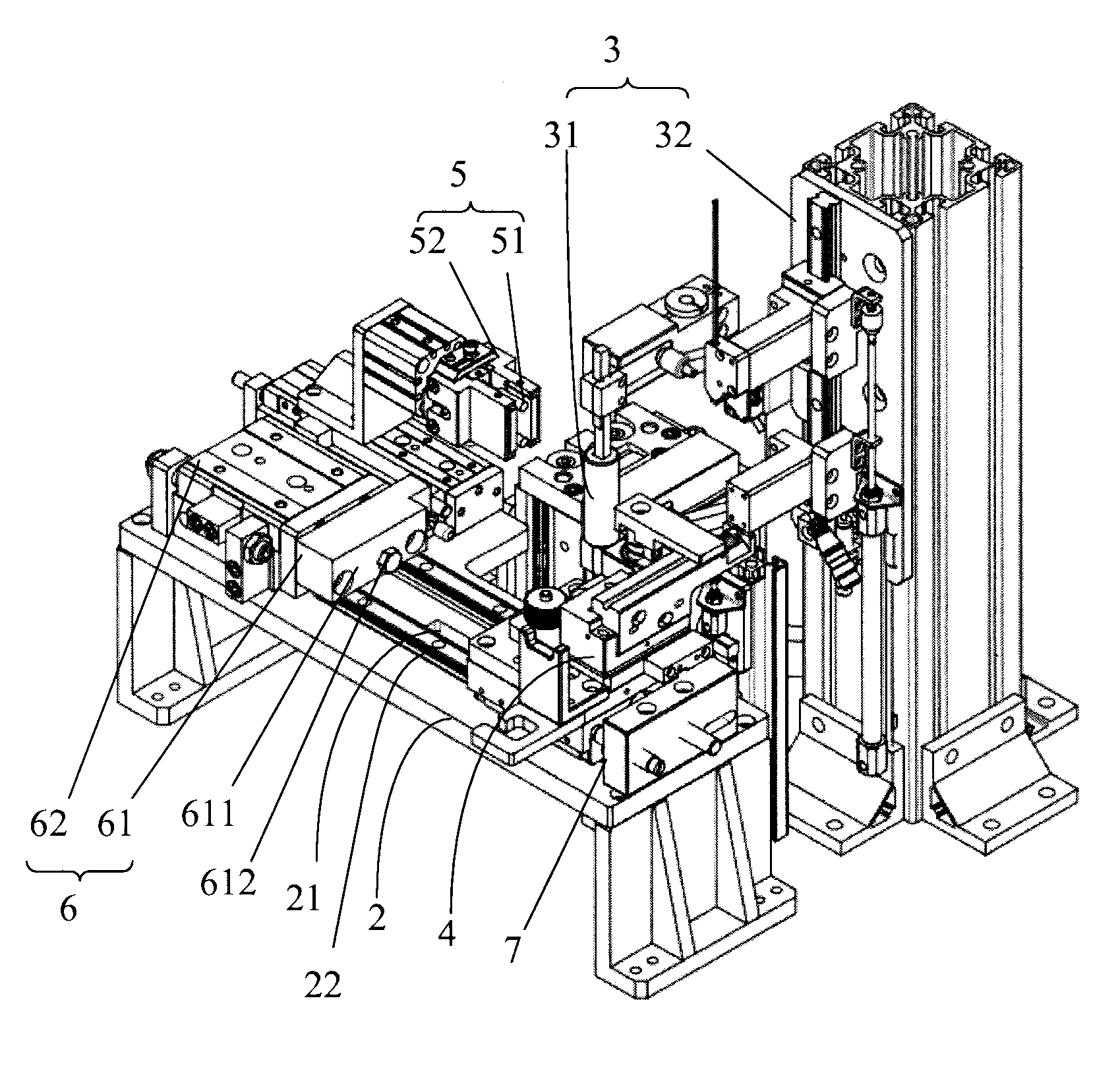
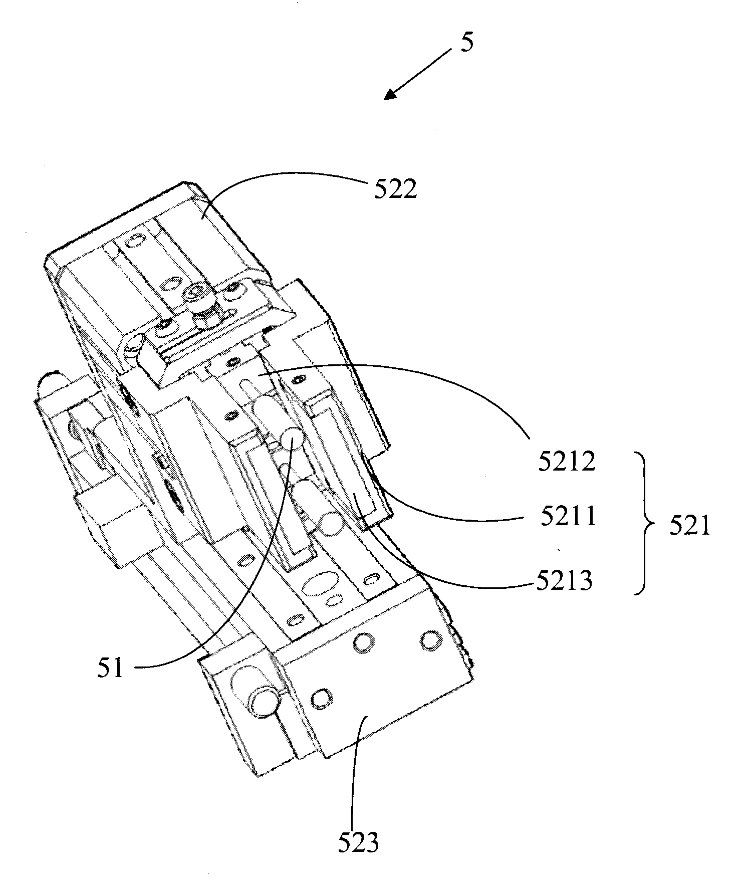
[0015] See figure 1 , a welding machine, including a base 2, a weldment clamping device 4 for clamping a weldment, a welding device 3 for welding a weldment, and a guide rail device 22 fixed on the base 2, a driving device 7, a limiter Positioning device 6 and cleaning electrode device 5, described welding device 3 comprises welding head 31 and the welding fixed support 32 that fixes this welding head 31, and welding fixed support 32 is positioned at base 2 side, and welding head 31 can move up and down to The weldment is welded, but it cannot be displaced left and right. The cleaning device 5 is used to clean the welding head 31. The cleaning device 5 has a cleaning component for cleaning the welding head 31. In this accompanying drawing, the The cleaning components include: a cleaning brush 51 and a cleaning sheet 5213 . When cleaning the welding head 31, the cleaning brush 51 and the cleaning sheet 5213 on the moving cleaning device 5 are used for cleaning, so as to preven...


PUM


Abstract

The invention relates to a welding machine. The welding machine comprises a base, a welding part clamping device which is fixed on the base and is used for clamping a welding part, a welding head which is used for welding the welding part, and a cleaning electrode device which is use for cleaning the welding head, wherein the cleaning electrode device comprises a cleaning brush which is used for cleaning the welding head, and a moving device which is used for fixing the cleaning brush and enabling the cleaning brush to be close to or far away from the welding head. According to the welding machine, the cleaning electrode device is arranged to clean the welding head, so that welding effects of next welding are prevented from being affected by residual soldering tin or other dirt produced after the welding head welds, and service life of the welding head is prolonged.

Description

technical field [0001] The invention relates to a welding machine. Background technique [0002] Welding is a common technique for joining metal parts by passing metal alloys under the action of heat. In this case, the metal alloy (also called solder) reaches a melting temperature which is lower than the melting temperature of the metal parts to be joined. During soldering, molten solder flows between two metal parts. Under favorable conditions, a strong, tight, corrosion-resistant, electrically and thermally conductive connection is obtained between the solder and the metal. [0003] When the era entered the era of mechanized production, in terms of welding technology, in order to increase welding output and reduce welding time, welding machines were born. The current welding machine generally includes a bracket, a base set in the bracket, a welding piece clamping device fixed on the base for clamping the welding piece, and a welding head for the welding piece. The weldi...

Claims


Application Information

Patent Timeline
Patent Type & Authority Applications(China)
IPC IPC(8): B23K37/00B08B1/02
Inventor 沈皓然
Owner SIP GOLDWAY TECH
Why Eureka
Try Eureka