Al technical title is built by PatSnap Al team. It summarizes the technical point description of the patent document.
A diluter, gas technology, applied in the fields of gas and gas/vapor mixing, chemical instruments and methods, dissolution, etc., can solve the problems of inability to provide on-site gas distribution, inability to dilute gas, and reduce gas accuracy, and achieve light weight and dilution. Wide concentration range, compact effect
Active Publication Date: 2014-12-24
QINGDAO ZHONGRUI INTELLIGENT INSTR
View PDF3 Cites 1 Cited by
Summary
Abstract
Description
Claims
Application Information
AI Technical Summary
This helps you quickly interpret patents by identifying the three key elements:
Problems solved by technology
Method used
Benefits of technology
Problems solved by technology
This type of instrument has the following problems: 1. With the increase of the dilution factor, the precision of the mixed gas will be greatly reduced, resulting in inaccurate gas distribution; 2. Due to the mass flow controller, it is impossible to control the gas containing oil, dust, water vapor, etc. 3. Unable to provide on-site gas distribution, low work efficiency
Method used
Image
Click on the blue label to locate the original text in one second.
Reading with bidirectional positioning of images and text.
Examples
Embodiment Construction
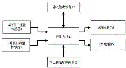
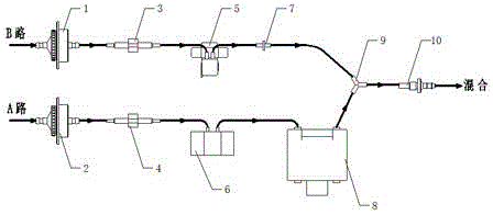
[0013] Such as figure 1 , 2 A gas diluter shown in the figure includes: A-way gas inlet 2, A-way orifice flow sensor 4, A-way gas capacity 6, A-way diaphragm pump 8, and B-way gas inlets 1, B Road orifice flow sensor 3, B-way diaphragm pump 5, B-way check valve 7, tee 9 connected to A-way diaphragm pump 8, B-way check valve 7, mixed gas outlet connected to the outlet of tee 9 10, and control system 11, input and output equipment 12, air pressure and temperature sensor 13; Described control system 11 connects A road orifice flow sensor 4, B road orifice flow sensor 3, A road diaphragm pump 8, B road diaphragm pump 5. Input and output devices 12, air pressure and temperature sensors 13.
[0014] Further, a filter membrane is installed inside the B-path gas inlet 1 .
[0015] Further, the A-way orifice flow sensor 4 and the B-way orifice flow sensor 3 are all electronic orifice flow sensors.
[0016] The control system 11 is mainly used to receive the flow signals of the A-wa...
PUM
Abstract
The invention discloses a gas dilutor. The gas dilutor comprises 1, an A path gas inlet, an A path orifice flow sensor, an A path air-capacitor and an A path diaphragm pump orderly connected, 2, a B path gas inlet, a B path orifice flow sensor, a B path diaphragm pump and a B path one-way valve orderly connected, 3, a three-way valve connected to the A path diaphragm pump and the B path one-way valve, 4, a mixed gas outlet connected to a gas outlet of the three-way valve, 5, a control system, 6, an input / output device, and 7, a gas pressure and temperature sensor. The control system is connected to the A path orifice flow sensor, the B path orifice flow sensor, the A path diaphragm pump, the B path diaphragm pump, the input / output device and the gas pressure and temperature sensor. The gas dilutor has a compact structure, a small volume and light weight, is convenient for carrying, has a high intelligentization degree, a wide diluted-concentration range, a high preparation precision and a high flow precision, and can be used for diluting special gas containing steam, dust and organics such as oil gas.
Description
technical field [0001] The invention relates to a gas diluter, which is used for generating gas with a specific dilution ratio, and is especially suitable for diluting special gas containing organic matter such as oil and gas, water vapor and dust. Background technique [0002] Existing gas diluters mainly use mass flow controllers to generate a mixed gas with a specific dilution ratio by controlling the flow. This type of instrument has the following problems: 1. With the increase of the dilution factor, the precision of the mixed gas will be greatly reduced, resulting in inaccurate gas distribution; 2. Due to the mass flow controller, it is impossible to control the gas containing oil, dust, water vapor, etc. 3. It is impossible to provide on-site gas distribution, and the work efficiency is low. [0003] Therefore, to provide a gas diluter that can accurately distribute gases containing special components such as oil, gas, dust, water vapor, etc., has a simple structure,...
Claims
Application Information
Patent Timeline
Application Date:The date an application was filed.
Publication Date:The date a patent or application was officially published.
First Publication Date:The earliest publication date of a patent with the same application number.
Issue Date:Publication date of the patent grant document.
PCT Entry Date:The Entry date of PCT National Phase.
Estimated Expiry Date:The statutory expiry date of a patent right according to the Patent Law, and it is the longest term of protection that the patent right can achieve without the termination of the patent right due to other reasons(Term extension factor has been taken into account ).
Invalid Date:Actual expiry date is based on effective date or publication date of legal transaction data of invalid patent.