Wireless sensor network node self-positioning method based on mobile anchor node
A wireless sensor, mobile anchor node technology, applied in wireless communication, network topology, electrical components and other directions, can solve the problem of high algorithm complexity, achieve the effect of simple algorithm, high positioning accuracy and low cost
- Summary
- Abstract
- Description
- Claims
- Application Information
AI Technical Summary
Problems solved by technology
Method used
Image
Examples
Embodiment 1
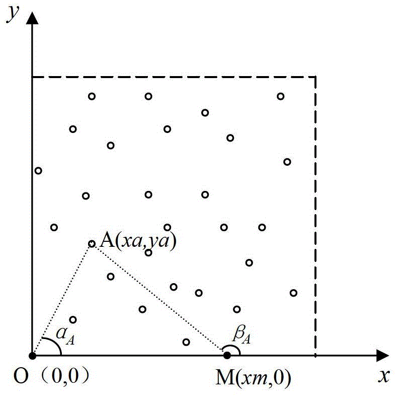
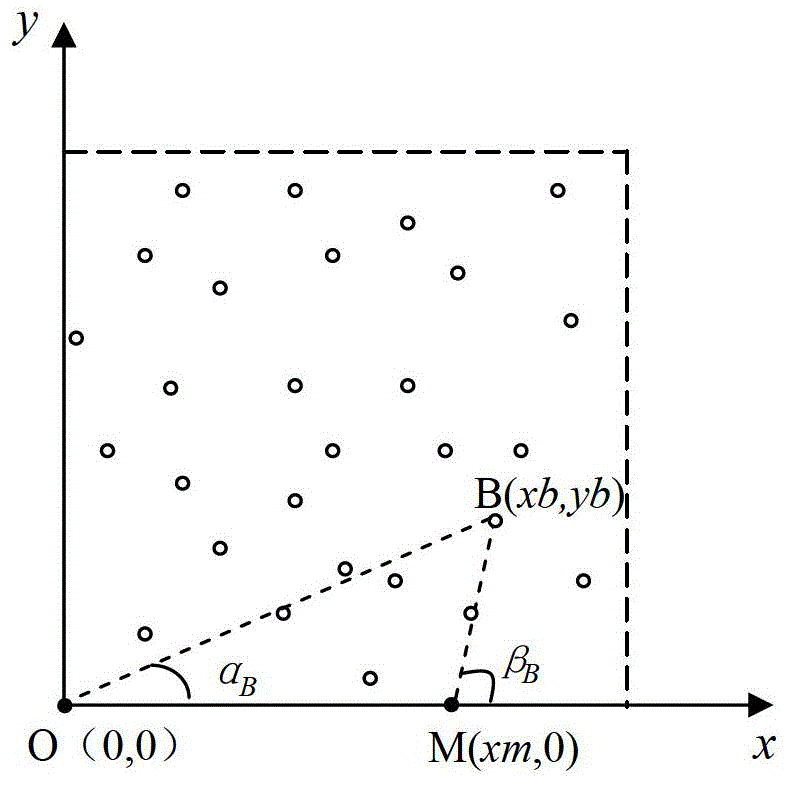
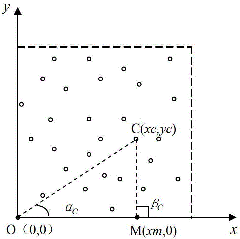
[0020] As shown in Figure 1, the anchor node moves along the x-axis to realize the positioning principle diagram. Figure 1 (a), (b), and (c) respectively represent the positioning principles of unknown nodes in several different situations. The dotted lines in the figure and the coordinates The area enclosed by the axis is the monitoring area, the hollow circle represents the sensor node (unknown node) that needs to be positioned, the solid circle on the coordinate axis represents the moving anchor node, unknown nodes A (xa, ya), B (xb, yb), C(xc, yc) respectively represent arbitrarily selected unknown nodes in several different situations, and the self-location method is explained through the self-location principle of unknown nodes A, B, and C. The positioning steps are as follows:
[0021] Step 1: The sensor nodes are randomly scattered in the monitoring area, and the nodes enter the waiting state after being thrown down;
[0022] Step 2: The base station applies a synchro...
Embodiment 2
[0038] Such as figure 2 As shown, two anchor nodes move along the x-axis and y-axis respectively to realize the positioning schematic diagram, wherein the first anchor node 201 moves along the x-axis, and the second anchor node 202 moves along the y-axis, and the positioning steps are as follows:
[0039] Step 1: The sensor nodes are randomly scattered in the monitoring area, and the nodes enter the waiting state after being thrown down;
[0040] Step 2: The base station applies a synchronization algorithm (such as the RBS synchronization algorithm) to realize the synchronization of the entire network, and then the unknown node enters a dormant state;
[0041] Step 3: Establish a two-dimensional planar Cartesian coordinate system, so that all sensor network monitoring areas are in the first quadrant, and place the first anchor node 201 at the coordinate origin O(0,0), and the first anchor node 201 is directional with the antenna The starting azimuth angle between the x-axis i...
Embodiment 3
[0058] Such as image 3 As shown, the realization method of sensor network hierarchical positioning. Assume that the network layer height is h to realize network layering, the size of h is determined according to information such as anchor node communication capability and network scale, and the layering line is parallel to the coordinate axis. The initial position of the anchor node is at the origin of the coordinates, and first moves along the positive direction of the x-axis. Using the method of Embodiment 1, the location of the unknown node on the first layer can be realized. When the anchor node reaches the network boundary, as image 3 At point O1, the anchor node turns to move upward along the direction of O1O2. When the anchor node reaches point O2, it moves to the left along the direction of O2O3 and enters the second layer of positioning until it reaches point O3 to complete the second layer of unknown node positioning, and then anchor The node then turns to move up...
PUM
 Abstract
Description
Claims
Application Information
 - R&D
- Intellectual Property
- Life Sciences
- Materials
- Tech Scout
- Unparalleled Data Quality
- Higher Quality Content
- 60% Fewer Hallucinations
Browse by: Latest US Patents, China's latest patents, Technical Efficacy Thesaurus, Application Domain, Technology Topic, Popular Technical Reports.
© 2025 PatSnap. All rights reserved.Legal|Privacy policy|Modern Slavery Act Transparency Statement|Sitemap|About US| Contact US: help@patsnap.com


