
Method for determining reduction factor of bearing capacity of axial load cylindrical shell structure

A determination method and technology of bearing capacity, applied in the field of determination of bearing capacity reduction factor of axial compression shell structure, can solve the problems of lack of clarity and adequacy, and high experimental cost.

Active Publication Date: 2013-06-12
DALIAN UNIV OF TECH
View PDF1 Cites 21 Cited by
  • Summary
  • Abstract
  • Description
  • Claims
  • Application Information

AI Technical Summary

Problems solved by technology

[0005] The purpose of the present invention is to propose a new method based on the most unfavorable multi-point disturbance in view of the shortcomings of the existing method for determining the reduction factor of the bearing capacity of the cylindrical shell structure, such as being too conservative, the cost of the experiment is large, and the lack of clear and sufficient physical meaning. The method for determining the reduction factor of the shell bearing capacity of the load mode, by introducing multi-point sag defects, and based on optimization techniques such as enumeration method, genetic algorithm or surrogate model, the most unfavorable multi-point disturbance load combination under a limited number of sags is obtained. The bearing capacity reduction factor of the axially compressed shell structure is determined. Compared with the traditional defect sensitivity evaluation method based on experimental experience represented by NASA SP-8007, it is more convenient for experimental verification, and has clearer physical meaning and more real Reliable Forecast Results

Method used


Image

  • Method for determining reduction factor of bearing capacity of axial load cylindrical shell structure
  • Method for determining reduction factor of bearing capacity of axial load cylindrical shell structure
  • Method for determining reduction factor of bearing capacity of axial load cylindrical shell structure

Examples


Embodiment 1

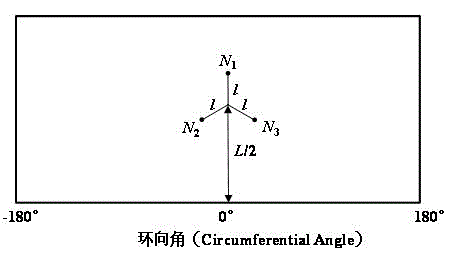
[0071] refer to Figure 4 with Figure 5 , the radius of the metal cylindrical shell R = 250 mm, length L = 510 mm, thickness t = 0.5 mm. The material is 2024 aluminum alloy: modulus of elasticity E = 72 GPa, Poisson's ratio υ = 0.31, yield stress σ s = 363 MPa, ultimate stress σ b = 463 MPa, density ρ = 2.8E-6 kg / mm 3 . In order to facilitate clamping and loading, T-rings are arranged at the bottom and top of the cylindrical shell, and the material is the same as that of the cylindrical shell. The bottom end of the T-ring is fixed, and the top end is fully restrained except for the axial translational displacement.

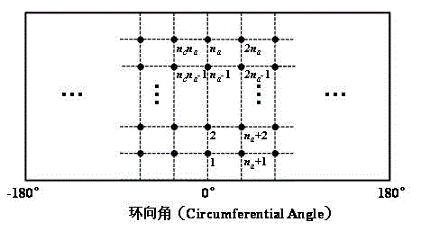
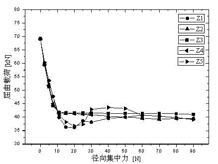
[0072] refer to Figure 6 , the radial concentrated force is applied to introduce the initial defect along the five equal parts of the axial direction, and the curves of the radial concentrated force and the buckling load value of the structure are drawn. Assuming that there is an initial defect (1.5mm) that is 3 times the thickness of th...

Embodiment 2

[0076] refer to Figure 11 with Figure 12 , the radius of the composite cylindrical shell R = 250 mm, length L = 510 mm. The layering of the cylindrical shell is [45 / -45 / 45 / -45 / 45], the thickness of the single layer is 0.1mm, and the material constant is: E 11 = 84.56 GPa, E 22 = 6.86 GPa, G 12 = G 13 = 4.9 GPa, G 23 = 1.96 GPa, υ 12 = 0.3, ρ = 1.7E-6 kg / mm 3 . In order to facilitate clamping and loading, T-rings are set at the bottom and top of the cylindrical shell, using 2024 aluminum alloy: modulus of elasticity E = 72 GPa, Poisson's ratio υ = 0.31, yield stress σ s = 363 MPa, ultimate stress σ b = 463 MPa, density ρ = 2.8E-6 kg / mm 3 . The bottom end of the T-ring is fixed, and the top end is fully restrained except for the axial translational displacement.

[0077] refer to Figure 13 , respectively apply radial concentrated force to introduce initial defects along the five equal parts of the axial direction, and draw the cu...

Embodiment 3

[0081] refer to Figure 18 with Figure 19 , the radius of the metal cylindrical shell R = 300 mm, length L = 600 mm, thickness t = 0.5 mm. The material is 2024 aluminum alloy: modulus of elasticity E = 72 GPa, Poisson's ratio υ = 0.31, yield stress σ s = 363 MPa, ultimate stress σ b = 463 MPa, density ρ = 2.8E-6 kg / mm 3 . In order to facilitate clamping and loading, T-rings are arranged at the bottom and top of the cylindrical shell, and the material is the same as that of the cylindrical shell. The bottom end of the T-ring is fixed, and the top end is fully restrained except for the axial translational displacement.

[0082] refer to Figure 20 , respectively apply radial concentrated force to introduce the initial defect along the six equal parts of the axial direction, and draw the curve of radial concentrated force and structural buckling load value Figure 21 . Assuming that there is an initial defect (1.5mm) that is three times the thickness ...


PUM


Abstract

The invention relates to the technical field of stability checking of main strength-bearing thin-walled members of aerospace and architectural structures, and discloses a method for determining a reduction factor of a bearing capacity of an axial load cylindrical shell structure, which is different from an experiment experience-based conventional defect sensitivity evaluating method with NASASP-8007 as a representative. Pit defect is introduced in a mode of applying a radial concentrated force (disturbance load). The method comprises the steps of: firstly, carrying out numerical analysis on an influence law of pit defect amplitude of a single point to the axial load bearing capacity of the axial load cylindrical shell shaft, and determining a reasonable load amplitude range; secondly, carrying out defect sensitivity analysis on pit defects of multiple points; thirdly, carrying out experiment design sampling by using load amplitude values and loading position distribution as design variables; and finally, based on optimizing technologies such as an enumeration method, a genetic algorithm and a surrogate model, searching the most disadvantageous disturbance loads limiting the defect amplitude in multiple points, and determining the reduction factor of the bearing capacity of the axial load cylindrical shell structure, so as to establish the more actual and reliable method for evaluating the defect sensitivity and the bearing performance of the axial load cylindrical shell structure, wherein the method has great physical significance.

Description

technical field [0001] The invention relates to the technical field of stability checking of main load-bearing thin-walled components of aerospace and building structures, in particular to a method for determining the reduction factor of the load-bearing capacity of an axially-compressed cylindrical shell structure. Background technique [0002] The rocket body structure needs to bear a huge take-off thrust during the launch phase, so the axial compression load is the most important design condition of its load-bearing structure. Although the propellant tank with all-metal grid reinforcement is used as a secondary load-bearing structure of the rocket body, it bears a huge axial pressure. Taking the CZ-5, a new generation of large-diameter launch vehicle with a core-level structure diameter of 5 meters being developed in my country as an example, only the all-metal grid-reinforced liquid oxygen tank with a diameter of 3.35 meters in its booster structure has a design axial pr...

Claims


Application Information

Patent Timeline
Patent Type & Authority Applications(China)
IPC IPC(8): G06F19/00
CPCB64C1/068G06F2113/28G06F2111/10G06F30/23Y02T90/00G01M99/007
Inventor 王博郝鹏李刚田阔杜凯繁方耀楚张希唐霄汉王斌骆洪志
Owner DALIAN UNIV OF TECH
Learn More