
Multichannel nano particle automatic infliction device for Raman spectrum

A nanoparticle and Raman spectroscopy technology, which is applied in Raman scattering, material excitation analysis, etc., can solve problems such as danger and circuit board damage, and achieve the effects of enhancing safety, improving efficiency and precision, and improving operational safety

Inactive Publication Date: 2015-01-14
XIAMEN UNIV
View PDF5 Cites 0 Cited by
  • Summary
  • Abstract
  • Description
  • Claims
  • Application Information

AI Technical Summary

Problems solved by technology

However, due to misoperation, etc., the sample being operated may flow into the circuit board, which may cause damage to the circuit board and even cause danger.

Method used


Image

  • Multichannel nano particle automatic infliction device for Raman spectrum
  • Multichannel nano particle automatic infliction device for Raman spectrum
  • Multichannel nano particle automatic infliction device for Raman spectrum

Examples


Embodiment 1

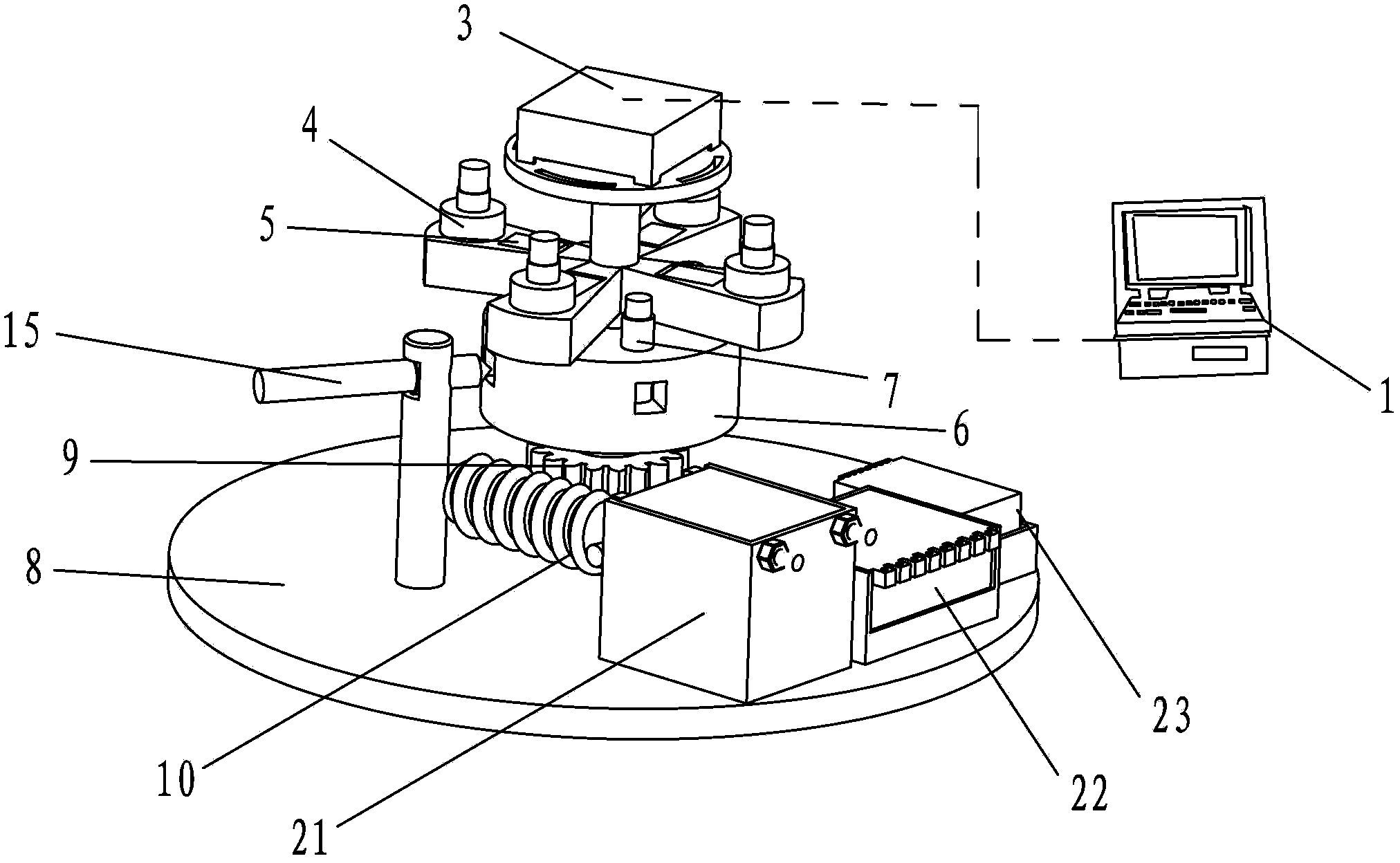
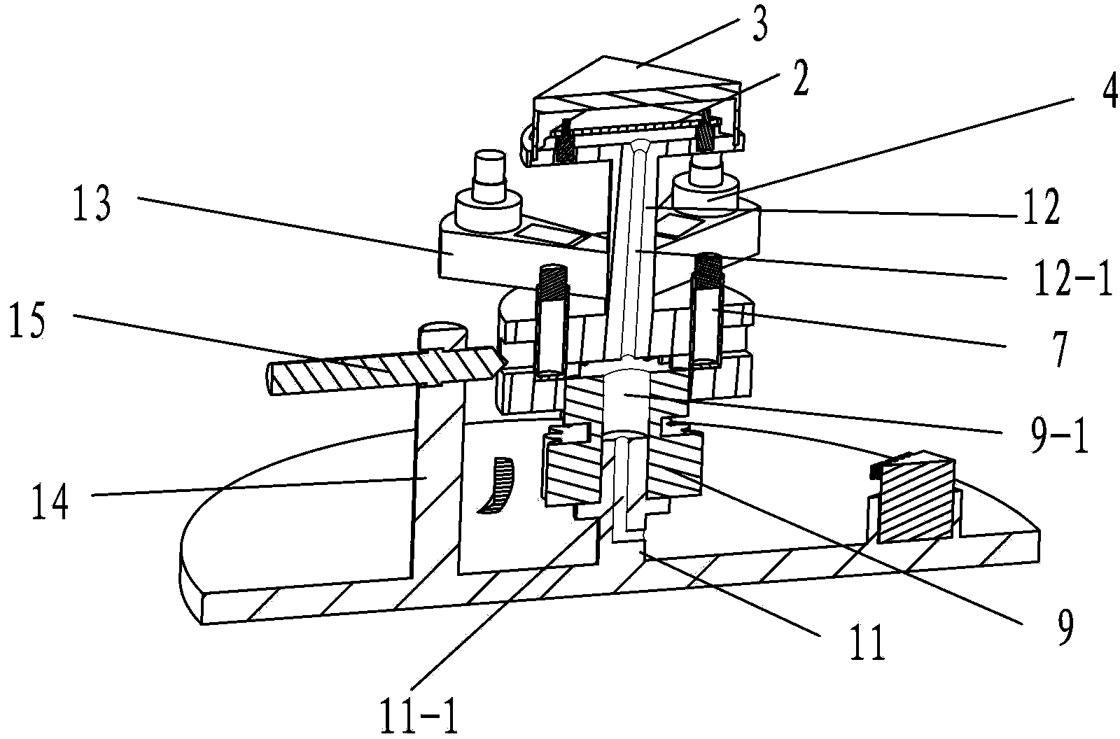
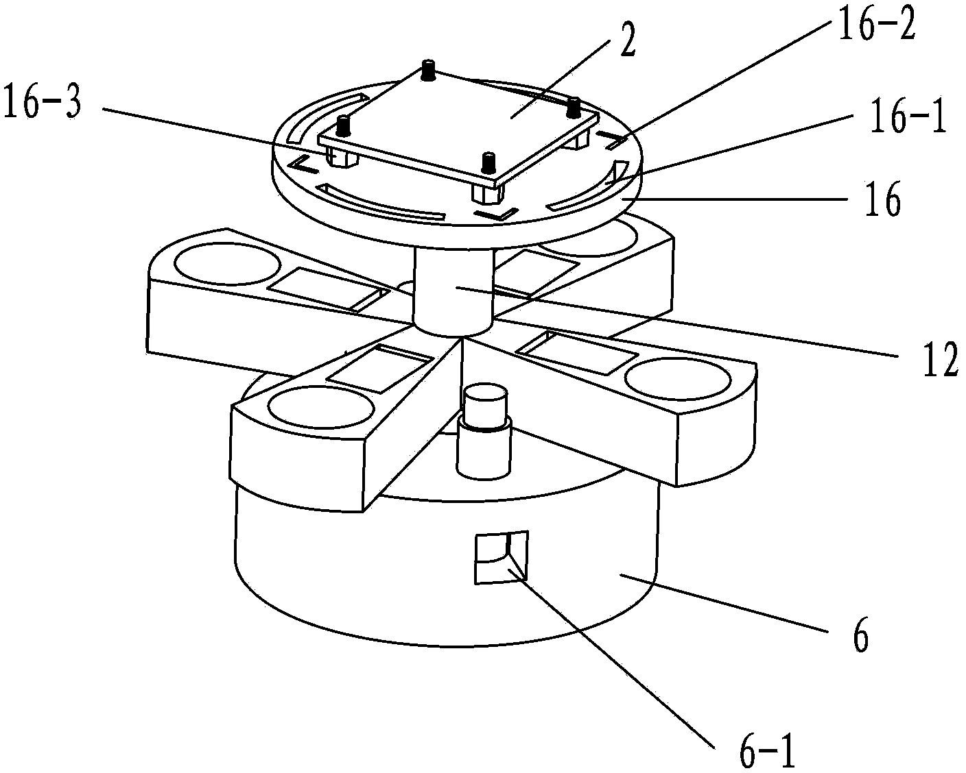
[0034] Such as Figure 1 to Figure 3 As shown, the multi-channel SHINERS particle automatic application device for the entire Raman spectrum includes a particle application unit, a control unit and a driving unit. Among them, the control unit includes computer 1, hardware control circuit 2, hardware circuit protection cover 3, etc.; the application unit includes sample bottle 4, pump 5, rotating body 6, detection bottle 7, base 8 (including fiber optic probe inlet bracket 14), etc.; The driving unit includes a worm gear and a spur gear 9, a worm 10, a stepping motor 21, a stepping motor driver 22, a switching power supply 23, and the like.

[0035] The base 8 is disc-shaped, and the outer edge of its upper surface is provided with a stepping motor 21 , a stepping motor driver 22 , a switching power supply 23 , and the stepping motor 21 is connected to the worm screw 10 .

[0036] A support shaft 11 is provided upwards in the center of the base, and the upper half of the suppo...

Embodiment 2

[0059] see Figure 4 , the composition and structure of this embodiment and embodiment 1 are basically the same, the difference is that in embodiment 1, there are only 4 sample vials 4 and 2 detection vials 7, and two detection holes 6-1. In this embodiment, each arm 13 is provided with two sample pools 4' and two pump chambers 5', and a detection bottle 7 and a detection hole 6-1 are respectively arranged between the four arms 13. Each arm corresponds to a vial, or adjacent arms each have a vial corresponding to a vial between the arms. In this way, 4 groups of samples can be measured at one time.

Embodiment 3

[0061] see Figure 5 , the basic mechanisms of this embodiment and embodiment 1 are basically the same, the difference is that in embodiment 1, there are four sample bottles 4 and two detection bottles 7, and two detection holes 6-1, while in this embodiment In the example, four sample bottles 4 and four detection bottles 7 are provided, and each detection bottle 7 is provided with a detection hole. The detection bottles 7 are spaced between the angles of the arms. This embodiment is suitable for the application of ordinary nanoparticles.


PUM


Abstract

The invention discloses a multiple nano particle automatic infliction device for Raman spectrum. The multiple nano particle automatic infliction device for the Raman spectrum comprises a particle infliction unit, a driving unit and a control unit, wherein the particle infliction unit comprises a rotating body, at least two sample bottles and at least two detecting bottles are arranged on the rotating body, a pump which is used for pumping samples in the sample bottles to the detecting bottles is arranged between the sample bottles and the detecting bottles, a support is arranged on the rotating body, an installation box which is used for installing a hardware control circuit of the control unit is arranged at the upper end of the support, the control unit comprises the hardware control circuit and a computer and controls the driving unit and the pump of the particle infliction unit to operate. The multiple nano particle automatic infliction device for the Raman spectrum enables a whole detecting process automation, meanwhile, liquid unexpectedly contacting electoral components can be avoided in the process of using the multiple nano particle automatic infliction device for Raman spectrum, and stability of a detecting device and operation safety can be improved.

Description

technical field [0001] The invention mainly relates to a control device for reducing manual participation and increasing automatic operation in the process of Raman spectrum detection, especially the detection process of samples by plasmon-enhanced Raman spectrum instruments. The utility model belongs to the field of automatic equipment for spectrum detection. Background technique [0002] Surface-enhanced Raman spectroscopy is a very powerful and highly sensitive analytical technique. It can detect and analyze various molecules adsorbed on the surface of a substance. For some systems, its sensitivity even reaches the single-molecule level. However, its application is very limited - only a few metals (gold, silver, copper) can produce such a strong surface-enhanced Raman scattering effect. [0003] Academician of the Chinese Academy of Sciences, Professor Tian Zhongqun's research group from the School of Chemistry and Chemical Engineering of Xiamen University proposed the e...

Claims


Application Information

Patent Timeline
Patent Type & Authority Patents(China)
IPC IPC(8): G01N21/65
Inventor 范贤光李帆许英杰吴丁贵胡振邦何坚王磊田中群
Owner XIAMEN UNIV
Learn More