
Attitude measurement method of micro-electro mechanical system (MEMS) inertial navigation system based on single-shaft forward revolution and reverse revolution

An inertial navigation system and measurement method technology, applied in the field of measurement, can solve the problems of constant value deviation of inertial devices, difficulty in improving attitude accuracy of inertial navigation system, etc.

Inactive Publication Date: 2013-06-12
LIAONING TECHNICAL UNIVERSITY
View PDF3 Cites 18 Cited by
  • Summary
  • Abstract
  • Description
  • Claims
  • Application Information

AI Technical Summary

Problems solved by technology

According to the basic principle of the inertial navigation system, the existence of the constant value deviation of the inertial device in the navigation process is the main factor that makes it difficult to improve the attitude accuracy of the inertial navigation system

Method used


Image

  • Attitude measurement method of micro-electro mechanical system (MEMS) inertial navigation system based on single-shaft forward revolution and reverse revolution
  • Attitude measurement method of micro-electro mechanical system (MEMS) inertial navigation system based on single-shaft forward revolution and reverse revolution
  • Attitude measurement method of micro-electro mechanical system (MEMS) inertial navigation system based on single-shaft forward revolution and reverse revolution

Examples


Embodiment Construction

[0046] The specific embodiment of the present invention is described in detail below in conjunction with accompanying drawing:

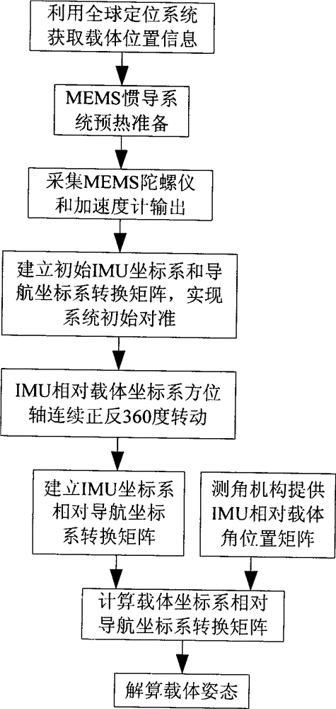
[0047] (1) Use the global positioning system to determine the initial position parameters of the carrier, and bind them to the navigation computer;

[0048] (2) After the MEMS inertial navigation system is preheated, the output data of the MEMS gyroscope and the MEMS accelerometer are collected;

[0049] (3) Determine the angle information between the IMU coordinate system and the navigation coordinate system according to the relationship between the carrier motion acceleration information measured by the MEMS accelerometer and the local gravitational acceleration and the relationship between the carrier angular velocity information output by the MEMS gyroscope and the earth's rotation angular rate, and complete The initial alignment process of the system, the establishment of the initial strapdown matrix of the MEMS inertial navigation system

[...


PUM


Abstract

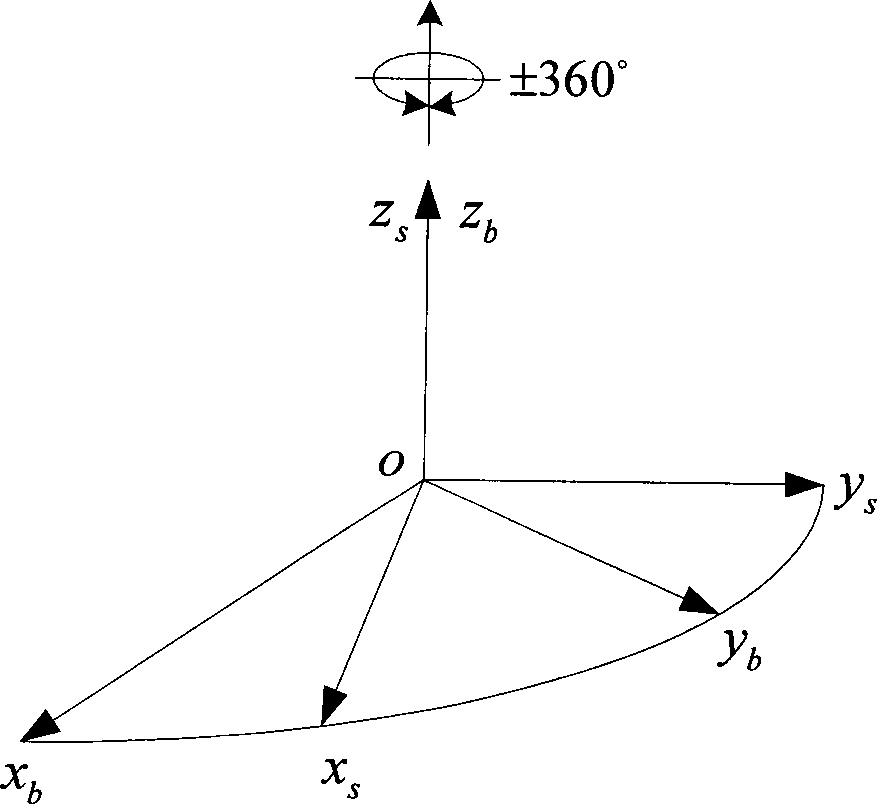
The invention provides an attitude measurement method of a micro-electro mechanical system (MEMS) inertial navigation system based on single-shaft forward revolution and reverse revolution. Initial position parameters of a carrier are determined by means of a global position system and are input into a navigational computer; after being pre-heated, an MEMS inertial navigation system collects output data of an MEMS gyroscope and output data of an MEMS accelerometer; according relationship between carrier motion acceleration information measured by the MEMS accelerometer and local gravity acceleration and relationship between carrier angular speed information output by the MEMS gyroscope and the earth rotation angular rate, angle information between an inertial measurement unit (IMU) coordinate system and a navigation coordinate system is determined, and an initial alignment process of the system is completed; the revolution scheme is that an IMU alternately revolves for 360 degrees forwards and reversely around a carrier coordinate system (b coordinate system) and a cycle is completed; an output value of the MEMS gyroscope under the revolution state of the IMU is plugged into the inertial navigation system, and a strapdown matrix is updated by quaternion algorithm; and according to a real-time revolution angle position of the IMU relative to the carrier provided by an angle measurement mechanism, a transfer matrix of the carrier coordinate system and the IMU coordinate system is built, and by means of combination of the transfer matrix and an attitude matrix, a transfer matrix of the carrier coordinate system relative to the navigation coordinate system is calculated. According to the method, modulation for constant deviation of an inertial component is carried out, and attitude precision of the system is improved.

Description

(1) Technical field [0001] The invention relates to a measurement method, in particular to a MEMS inertial navigation system attitude measurement method based on single-axis forward and reverse rotation. (2) Background technology [0002] Micro-electro-mechanical systems (MEMS) have undergone years of continuous development since they were proposed in the mid-1950s. The inertial navigation system composed of MEMS devices is widely used in the environment of short-time work because of its low cost and the disadvantage of large device deviation. According to the basic principle of the inertial navigation system, the existence of the constant value deviation of the inertial device in the navigation process is the main factor that makes it difficult to improve the attitude accuracy of the inertial navigation system. How to effectively limit the error divergence of inertial navigation and improve the attitude measurement accuracy of inertial navigation system is an important top...

Claims


Application Information

Patent Timeline
Patent Type & Authority Applications(China)
IPC IPC(8): G01C21/16
Inventor 孙伟王大雪徐龙威徐令令沈培培
Owner LIAONING TECHNICAL UNIVERSITY
Learn More