
Cab frame structure for construction machine

A technology of frame structure and construction machinery, applied in the direction of building, superstructure, sub-assembly of superstructure, etc., can solve problems such as height restrictions, and achieve the effect of improving the installation position and expanding the viewing angle from above.

Active Publication Date: 2013-06-05
PRESS KOGYO CO LTD
View PDF4 Cites 2 Cited by
  • Summary
  • Abstract
  • Description
  • Claims
  • Application Information

AI Technical Summary

Problems solved by technology

Therefore, the height of the front roof beam 4 arranged to coincide with the position of the upper end 7x of the front window unit 7 is limited, and the driver's upward viewing angle θ1 is limited by the front roof beam 4 .

Method used


Image

  • Cab frame structure for construction machine
  • Cab frame structure for construction machine
  • Cab frame structure for construction machine

Examples


Embodiment Construction

[0036] Preferred embodiments of the present invention will be described with reference to the drawings.

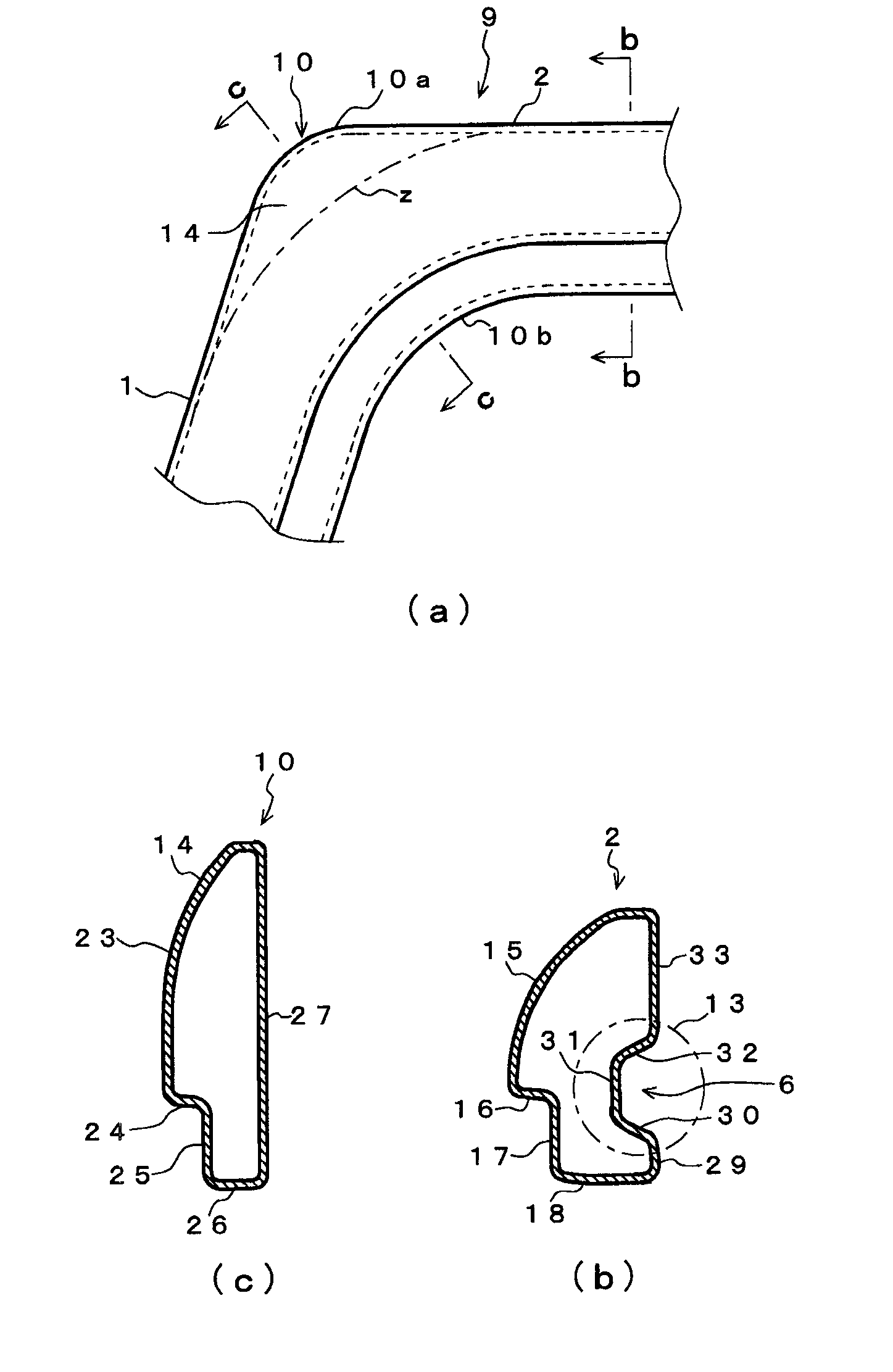
[0037] Such as Figure 5 As shown, the cab frame structure of the construction machine in this embodiment has and uses figure 1 and figure 2 With the same constituent elements as those already described, the front pillar 1 and the top pillar 2 constituting the frame of the cab are composed of a single pipe 9 having a bent portion 10 at the junction of these front pillars 1 and top pillar 2 . Therefore, the same components are denoted by the same reference numerals and their descriptions are omitted, and only the different points, that is, the features, will be described.

[0038] Such as Figure 5 As shown, the cab frame structure of the present embodiment is characterized in that the radius of curvature of the curved outer side 10a of the curved portion 10 of the pipe material 9 is smaller than the radius of curvature of the curved inner side 10b, thereby setting the cu...


PUM


Abstract

Provided is a cab frame structure for a construction machine, the cab frame structure having front pillars and roof pillars with each of the front pillars and the corresponding roof pillar configured from a single pipe material, the cab frame structure enabling a front header to be installed as high as possible in order to increase the upward viewing angle of the operator. The cab frame of a construction machine has front pillars (1) and roof pillars (2) with each of the front pillars (1) and the corresponding roof pillar (2) configured from a single pipe material (9) having a curved section (10) at the joint between the front pillar (1) and the roof pillar (2), and the curvature radius of the curved section (10) at the curve outer side (10a) thereof is set to be smaller than the curvature radius at the curve inner side (10b) thereof. As a result, spaces (12) which enable the position for containing the upper end (7x) of a front window unit (7) to be raised are formed in the curved sections (10). A front header (4) is disposed in such a manner that the position thereof corresponds to that of the upper end (7x) of the front window unit (7), the upper end (7x) being contained in the spaces (12). The configuration enables the front header (4) to be installed as high as possible to increase the upward viewing angle (?2) of the operator.

Description

technical field [0001] The present invention relates to a cab frame structure of a construction machine, wherein the front pillar and the top pillar constituting the cab frame of the construction machine are composed of a bent pipe. Background technique [0002] Such as figure 1 and figure 2 As shown, the cab frame structure of a construction machine generally includes: left and right front pillars 1 arranged upright in front of the cab (driver's seat); The rear end is connected to the rear column 3 extending downward from here; the front top beam 4 is arranged on the upper part of the front column 1 in a manner of erecting the left and right front columns 1; and is arranged in a manner of erecting the left and right rear columns 3 The rear top beam 5 on the top of the rear column 3. [0003] A guide rail 6 is provided on the front pillar 1 and the top pillar 2 , and a guided member 8 (eg, a guide roller, a protrusion, etc.) is engaged with the guide rail 6 , and the gui...

Claims


Application Information

Patent Timeline
Patent Type & Authority Applications(China)
IPC IPC(8): E02F9/16B62D25/08
CPCE02F9/16E02F9/163B60J1/004
Inventor 近藤茂树佐藤正则
Owner PRESS KOGYO CO LTD
Learn More