
Heater system of fuel filter

A fuel filter and heater technology, which is applied to fuel heat treatment devices, charging systems, filtration and separation, etc., can solve problems such as installation location and structural size limitations of thermal switches 14, enhance safety functions, and reduce production costs. , easy to produce effect

Inactive Publication Date: 2013-06-05
HYUNDAI MOTOR CO LTD +1
View PDF6 Cites 0 Cited by
  • Summary
  • Abstract
  • Description
  • Claims
  • Application Information

AI Technical Summary

Problems solved by technology

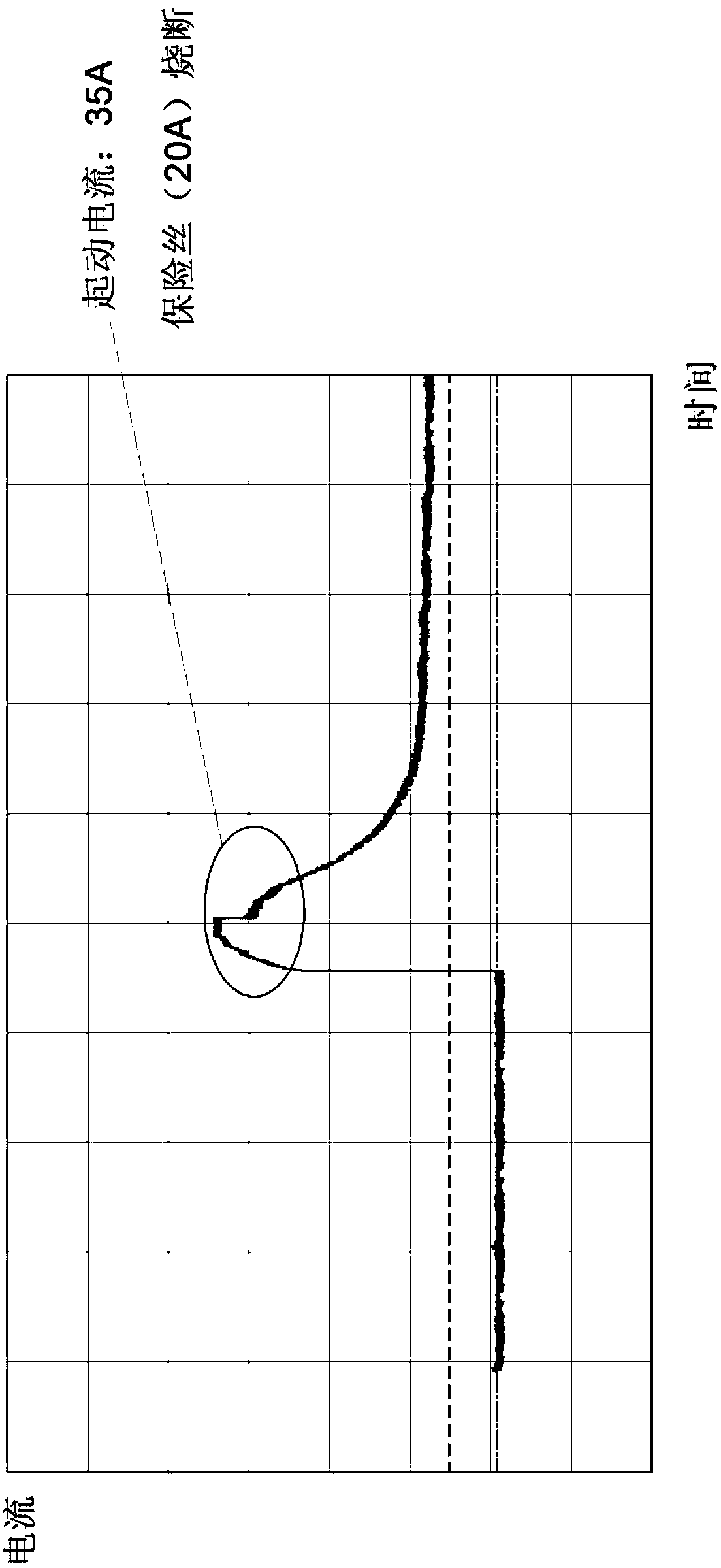
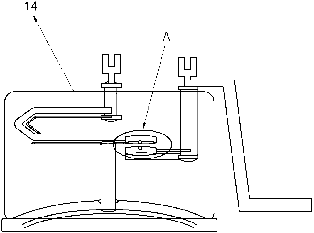
[0006] Further, the fuel filter heater system 10 according to the background art has limitations in design because the installation position and structural size of the thermal switch 14 are limited

Method used


Image

  • Heater system of fuel filter
  • Heater system of fuel filter
  • Heater system of fuel filter

Examples


Embodiment Construction

[0031] Reference will now be made in detail to various embodiments of the invention, examples of which are illustrated in the accompanying drawings and described below. While the invention will be described in conjunction with exemplary embodiments, it will be understood that present description is not intended to limit the invention to those exemplary embodiments. On the contrary, the invention is intended to cover not only the exemplary embodiments, but also various alternatives, modifications, equivalents and other embodiments, which may be included within the spirit and scope of the invention as defined by the appended claims .

[0032] Hereinafter, a heater system for a fuel filter according to an exemplary embodiment of the present invention will be described with reference to the accompanying drawings. Figure 4 is a schematic circuit diagram of a heater system of a fuel filter according to an exemplary embodiment of the present invention.

[0033] refer to Figure 4...


PUM


Abstract

The heater system of a fuel filter includes: a power supply unit supplying power; a lead wire unit receiving power from the power supply unit and having a plurality of branch lines to divide current of the supplied power; and a fuel filter having a plurality of internal thermo switches connected to the branch lines of the lead wire unit, respectively, and a PTC heater heated by power supplied through the internal thermo switches.

Description

[0001] Cross References to Related Applications [0002] This application claims priority from Korean Patent Application No. 10-2011-0126782 filed on Nov. 30, 2011, the entire contents of which are hereby incorporated by reference for all purposes. technical field [0003] The present invention relates to a heater system for a fuel filter, and more particularly, the present invention relates to a heater system for a fuel filter using a heater and a thermal switch. Background technique [0004] The fuel filter heater system 10 according to the background art has such figure 1 structure shown. In this structure, when a thermal switch 14 provided in the fuel filter 12 is turned on at a predetermined temperature or lower, a PTC (Positive Temperature Coefficient) heater 16 is connected to a power source and then operates. When the fuel is heated by the PTC heater 16, the thermal switch 14 is turned off at a predetermined temperature or higher in order to stop heating. [0005]...

Claims


Application Information

Patent Timeline
Patent Type & Authority Applications(China)
IPC IPC(8): F02M37/22F02M31/125
CPCY02T10/126F02M31/125F02M37/223F02M37/22F02M37/30Y02T10/12B01D35/18
Inventor 金兑映林钟佶
Owner HYUNDAI MOTOR CO LTD
Learn More