
Heat exchanger for catalytic cracking of heat recovery fuel

A catalytic cracking and heat recovery technology, which is applied in catalytic cracking, indirect heat exchangers, heat exchanger types, etc., can solve the problems of small cross-sectional area of ​​fuel steam circulation, large catalytic reaction space velocity, and difficulty in catalyst replacement, achieving improved Energy recovery benefit, energy recovery efficiency improvement, volume improvement effect

Inactive Publication Date: 2014-09-17
HUNAN UNIV
View PDF8 Cites 0 Cited by
  • Summary
  • Abstract
  • Description
  • Claims
  • Application Information

AI Technical Summary

Problems solved by technology

The heat exchange tubes in many such catalytic cracking units adopt straight tubes, and some use serpentine tubes. The cross-sectional area of ​​the fuel vapor flow is small and the flow resistance is large, which limits the volume of the catalyst. The catalytic reaction space velocity is large and the conversion rate is low; In addition, it is difficult to replace the catalyst, the service life of the equipment is short, and the maintenance cost is high

Method used


Image

  • Heat exchanger for catalytic cracking of heat recovery fuel
  • Heat exchanger for catalytic cracking of heat recovery fuel
  • Heat exchanger for catalytic cracking of heat recovery fuel

Examples


Embodiment 1

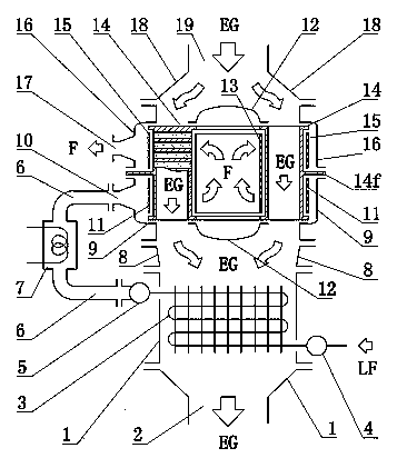
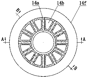
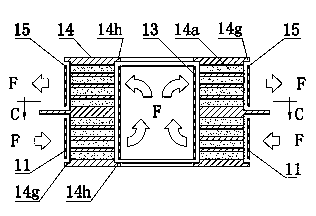
[0029] refer to Figure 1-Figure 5, the present embodiment includes a heat recovery fuel vaporizer 3, an electric auxiliary heater 7 and a heat recovery fuel catalytic cracking unit; the heat recovery fuel catalytic cracking unit includes a cylinder type catalytic cracker core 14, a fuel inlet section shell 9 and a fuel Exhaust section casing 16, the cylinder type catalytic cracker core body 14 is provided with an inner chamber (cylindrical shape), both ends of the inner chamber are equipped with end caps 12, the cylinder type catalytic cracker core body 14 The cylinder wall is provided with catalyst filling holes 14a, and the catalyst filling holes 14a are connected with the inner and outer surfaces of the cylinder wall. The circumferential direction of the body wall is dispersedly arranged to form a hole array, and the axial thermal fluid (such as the exhaust gas from the engine) passage 14b is arranged between the adjacent hole rows in the cylinder wall, and the axial therm...

Embodiment 2

[0036] refer to Figure 6 , the difference between this embodiment and Embodiment 1 is that: the shown heat recovery fuel catalytic cracking unit is two, that is, the first heat recovery fuel catalytic cracking unit and the second heat recovery fuel catalytic cracking unit, the first heat recovery fuel catalytic cracking unit The fuel catalytic cracking unit is connected in series with the second heat recovery fuel catalytic cracking unit, that is, the hot fluid outlet of the first heat recovery fuel catalytic cracking unit is connected with the hot fluid inlet of the second heat recovery fuel catalytic cracking unit, and the second heat recovery The fuel exhaust port of the fuel catalytic cracking unit is connected with the fuel inlet port of the first heat recovery fuel catalytic cracking unit.

[0037] The working principle and features of this embodiment are basically the same as those of Embodiment 1, but the catalytic cracking efficiency can be improved.

[0038] Of cou...


PUM


Abstract

The invention relates to a heat exchanger for catalytic cracking of a heat recovery fuel. The heat exchanger comprises a heat recovery fuel catalytic cracking unit, wherein the heat recovery fuel catalytic cracking unit comprises a cylindrical catalytic cracker core, a fuel inlet section shell and a fuel outlet section shell, wherein the cylindrical catalytic cracker core is internally provided with an inner cavity; end covers are mounted at two ends of the inner cavity; catalyst filling holes are formed in a cylinder wall; the catalyst filling holes are respectively communicated with inner and outer surfaces of the cylinder wall; the catalyst filling holes are formed side by side along the axis direction of the cylinder wall to form hole rows; the hole rows are separately distributed along the peripheral direction of the cylinder wall to form a hole array; axial hot fluid channels are arranged between adjacent hole rows; the axial hot fluid channels are communicated with the two ends of a cylinder; the cylindrical catalytic cracker core is provided with an externally annular partition plate; and the cylindrical catalytic cracker core is divided into a fuel inlet section and a fuel outlet section by the externally annular partition plate. The heat exchanger has large fuel vapor flowing sectional area, small flowing resistance, low catalytic reaction airspeed and high transformation rate, and a catalyst is easy to replace.

Description

technical field [0001] The invention relates to a fuel catalytic cracking heat exchanger for heat recovery, in particular to a fuel catalytic cracking heat exchanger utilizing waste heat of engine exhaust gas. Background technique [0002] Improving engine efficiency or developing clean alternative engine fuels are of great positive significance to energy conservation and environmental protection. Recovering engine waste heat to realize fuel cracking can increase the calorific value of fuel, improve engine efficiency, and also help to promote the development and utilization of clean alternative engine fuels. [0003] When the engine is working, the exhaust temperature is often in the range of 300-700 °C, and the waste heat energy of the exhaust gas is large. Recovering the waste heat of the engine is of great significance to energy saving. [0004] Certain fuels can be endothermicly cracked at high temperatures to increase the calorific value of the fuel, which is an effect...

Claims


Application Information

Patent Timeline
Patent Type & Authority Patents(China)
IPC IPC(8): F02M25/12C10G11/00F28D7/00
CPCY02T10/121Y02T10/12
Inventor 任承钦廖诚付建勤刘敬平
Owner HUNAN UNIV
Learn More