
Power system with hot-swap and the method thereof

A power system, hot-swap technology, used in control/regulation systems, output power conversion devices, conversion of DC power input to DC power output, etc. Achieve the effect of optimizing thermal design and reducing power loss

Active Publication Date: 2013-05-29
CHENGDU MONOLITHIC POWER SYST
View PDF6 Cites 3 Cited by
  • Summary
  • Abstract
  • Description
  • Claims
  • Application Information

AI Technical Summary

Problems solved by technology

Although the start-up period of the power system is very short compared to its entire operation period, the power dissipation on this MOSFETM1 increases the thermal design requirements of the system
Especially in high current applications, multiple MOSFETs and a lot of board space will be used for heat dissipation, thus wasting the thermal design under normal system operation

Method used


Image

  • Power system with hot-swap and the method thereof
  • Power system with hot-swap and the method thereof
  • Power system with hot-swap and the method thereof

Examples


Embodiment Construction

[0023] Specific embodiments of the present invention will be described in detail below. It should be noted that the embodiments described here are only used for illustration and are not used to limit the present invention. In the following description, in order to provide a thorough understanding of the present invention, numerous specific details are set forth. However, it is obvious to a person of ordinary skill in the art that it is not necessary to adopt these specific details to implement the present invention. In other instances, in order to avoid obscuring the present invention, well-known circuits, materials or methods are not specifically described.

[0024] Throughout the specification, references to "one embodiment," "an embodiment," "an example," or "example" mean that a specific feature, structure, or characteristic described in conjunction with the embodiment or example is included in the present invention In at least one embodiment. Therefore, the phrases "in one...


PUM


Abstract

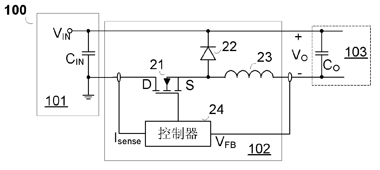
The present disclosure discloses a power system with hot-swap with a buck converter. The power system comprises a front stage, a hot-swap stage and a load stage; wherein the hot-swap stage comprises: a buck converter having a switch operate at ON / OFF state to provide a desired output voltage to the load stage with low power loss and optimized thermal design.

Description

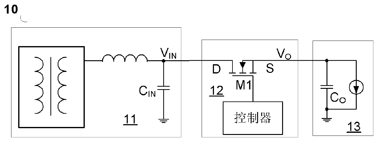
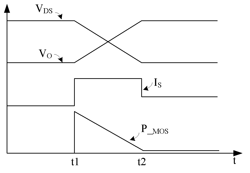
Technical field [0001] The present invention relates to an electronic circuit, and more specifically, the present invention relates to a live plug (hot plug) power system and method thereof. Background technique [0002] Hot-swappable technology is often used when inserting hard disk drives, boards, etc., or removing the above-mentioned peripheral devices from the running system. The prior art usually uses field effect transistors operating in low dropout mode as hot plugging, such as Figure 1a Shown. [0003] Figure 1a The circuit structure diagram of the existing hot-plug power system 10 is shown. Figure 1a The illustrated hot-swappable power system 10 includes: providing a supply voltage V IN The front stage 11, the front stage 11 includes the front stage capacitor C IN ; Hot-swappable stage 12, coupled to the previous stage 11 to receive the supply voltage V IN , And based on the supply voltage V IN Provide output voltage V O ; Load stage 13, coupled to the hot plug stage 1...

Claims


Application Information

Patent Timeline
Patent Type & Authority Applications(China)
IPC IPC(8): H02M3/00H02M3/156H02M3/157
CPCH02M3/157H02M3/00H02M3/156H02H9/001
Inventor 杨先庆李正兴任远程
Owner CHENGDU MONOLITHIC POWER SYST
Learn More