
Light source module and lighting device

A light source module and light emitting device technology, which is applied in the direction of light source, electric light source, lighting device, etc., can solve the problems of light leakage and brightness reduction of light emitting devices, and achieve the effect of reducing bright spots and light leakage

Inactive Publication Date: 2016-05-11
HONG FU JIN PRECISION IND (SHENZHEN) CO LTD +1
View PDF7 Cites 0 Cited by
  • Summary
  • Abstract
  • Description
  • Claims
  • Application Information

AI Technical Summary

Problems solved by technology

[0002] At present, many electronic devices need light source lighting. In order to reduce the space occupied by the light source, the point light source or line light source is usually expanded into a surface light source through the light guide plate. However, there is usually a gap between the light source and the light guide plate due to installation errors, and such a gap It will cause light leakage, which will reduce the luminance of the entire light emitting device

Method used


Image

  • Light source module and lighting device
  • Light source module and lighting device
  • Light source module and lighting device

Examples


Embodiment Construction

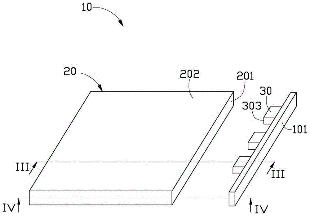
[0016] see figure 1 , the embodiment of the present invention provides a light emitting device 10, the light emitting device 10 includes a light guide plate 20, the light guide plate 20 is made of PMMA, PC plastic or other transparent materials, and its refractive index range is 1.47~1.55, the light guide plate 20 includes a light incident surface 201 and a light exit surface 202. In this embodiment, the light incident surface 201 and the light exit surface 202 intersect perpendicularly. The light incident surface 201 is the side of the light guide plate 20 with a small area. The light emitting surface 202 is a top surface with a larger area of ​​the light guide plate 20 .

[0017] The lighting device 10 also includes a plurality of light source modules 30. In this embodiment, three light source modules are taken as an example. Glossy 201.

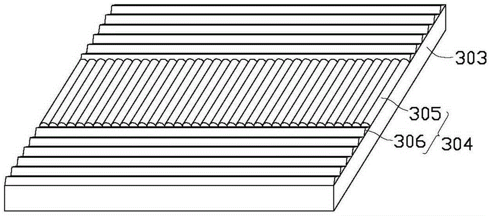
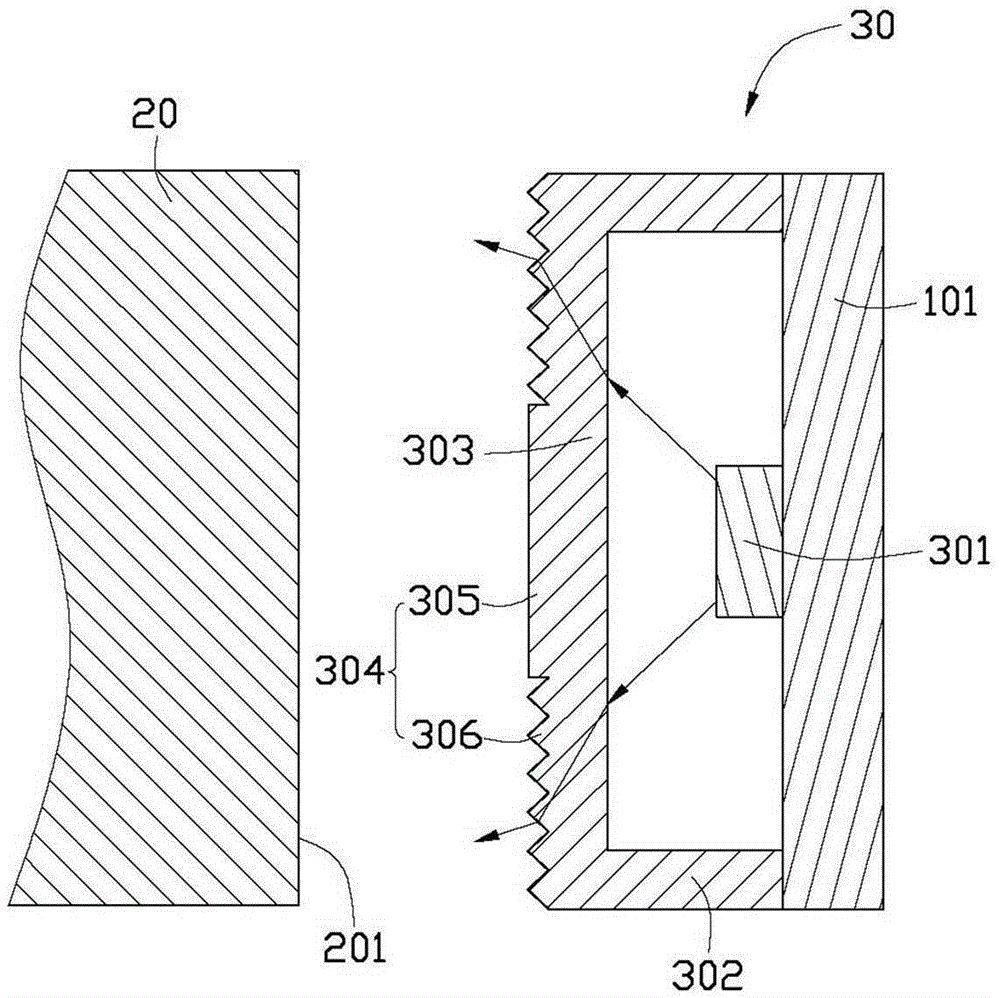
[0018] see Figure 2 to Figure 4 , each light source module 30 includes a light source 301 and a housing 302 , the material of the hou...


PUM


Abstract

The invention provides a light source module assembly which includes a shell body and a light source. The shell body is provided with a transparent light-emitting side which is arranged at the position corresponding to the light source. A microstructure is arranged on the outer surface of the transparent light-emitting side away from the light source, and the microstructure includes plural first light-guiding cylinders and plural second light-guiding cylinders which are protruded relatively to the outer surface. The first light-guiding cylinders are arranged in the middle of the outer surface, and the second light-guiding cylinders are arranged on both sides of the first light-guiding cylinders. The first light-guiding cylinders and the second light-guiding cylinders extend along the outer surface and are perpendicular to each other. The first light-guiding cylinders and the section perpendicular to an extension direction are in a semicircular shape, and the second light cylinder and the section perpendicular to the extension direction are in a triangular shape. The invention further discloses a light emitting device which utilizes the light source module.

Description

technical field [0001] The invention relates to a light emitting device and a light source module thereof. Background technique [0002] At present, many electronic devices need light source lighting. In order to reduce the space occupied by the light source, the point light source or line light source is usually expanded into a surface light source through the light guide plate. However, there is usually a gap between the light source and the light guide plate due to installation errors, and such a gap It will cause light leakage, thereby reducing the luminance of the entire light emitting device. In addition, because the light emitted by the point light source is relatively concentrated, the phenomenon of "bright spots" usually appears on the light-emitting surface of the light guide plate, that is, the brightness of some areas is higher than that of other areas. Contents of the invention [0003] In view of this, it is necessary to provide a light source module and a l...

Claims


Application Information

Patent Timeline
Patent Type & Authority Patents(China)
IPC IPC(8): F21S2/00F21V8/00F21K9/20F21K9/61F21Y115/10
Inventor 王何立颖
Owner HONG FU JIN PRECISION IND (SHENZHEN) CO LTD
Learn More