
High-pressure gear pump floating side plate with pressing plate

A floating side plate, gear pump technology, applied in the direction of rotary piston type/swing piston type pump components, pump elements, machines/engines, etc. Hydraulic gear pump mechanical efficiency and other issues, to achieve the effect of improving sealing effect, enhancing sealing effect and safety performance, improving reliability and service life

Active Publication Date: 2013-05-29
XUZHOU KEYUAN HYDRAULIC
View PDF8 Cites 10 Cited by
  • Summary
  • Abstract
  • Description
  • Claims
  • Application Information

AI Technical Summary

Problems solved by technology

[0003] With the increase of the pressure level, the existing hydraulic gear pumps face the following problems: First, the radial unbalanced force on the main and slave gear shafts of the hydraulic gear pump is greatly increased, which requires the gear shaft to be structurally optimized to reduce the radial force imbalance. The deflection deformation caused by the balance force, or changing the material of the gear shaft to improve its mechanical properties; second, the formation and maintenance of the friction pair between the floating side plate and the gear end face of the hydraulic gear pump under high temperature, high pressure and high speed becomes more and more difficult
Under ultra-high pressure, increasing the compression amount of the seal to achieve float compensation will greatly reduce the mechanical efficiency of the hydraulic gear pump

Method used


Image

  • High-pressure gear pump floating side plate with pressing plate
  • High-pressure gear pump floating side plate with pressing plate
  • High-pressure gear pump floating side plate with pressing plate

Examples


Embodiment Construction

[0019] Below in conjunction with embodiment the present invention is further described.

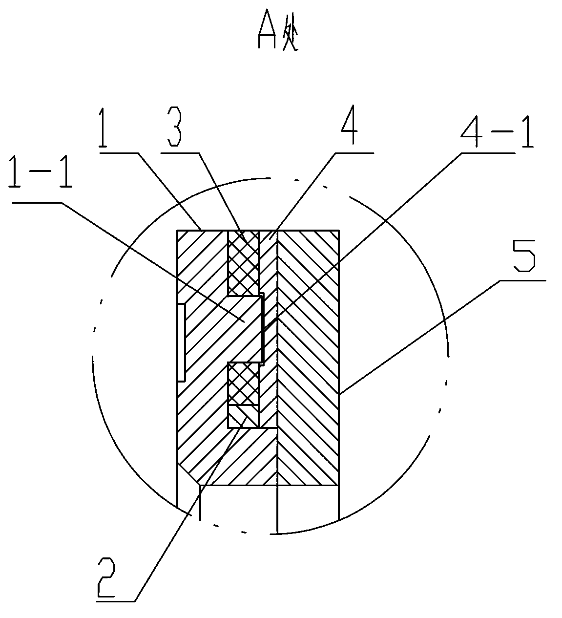
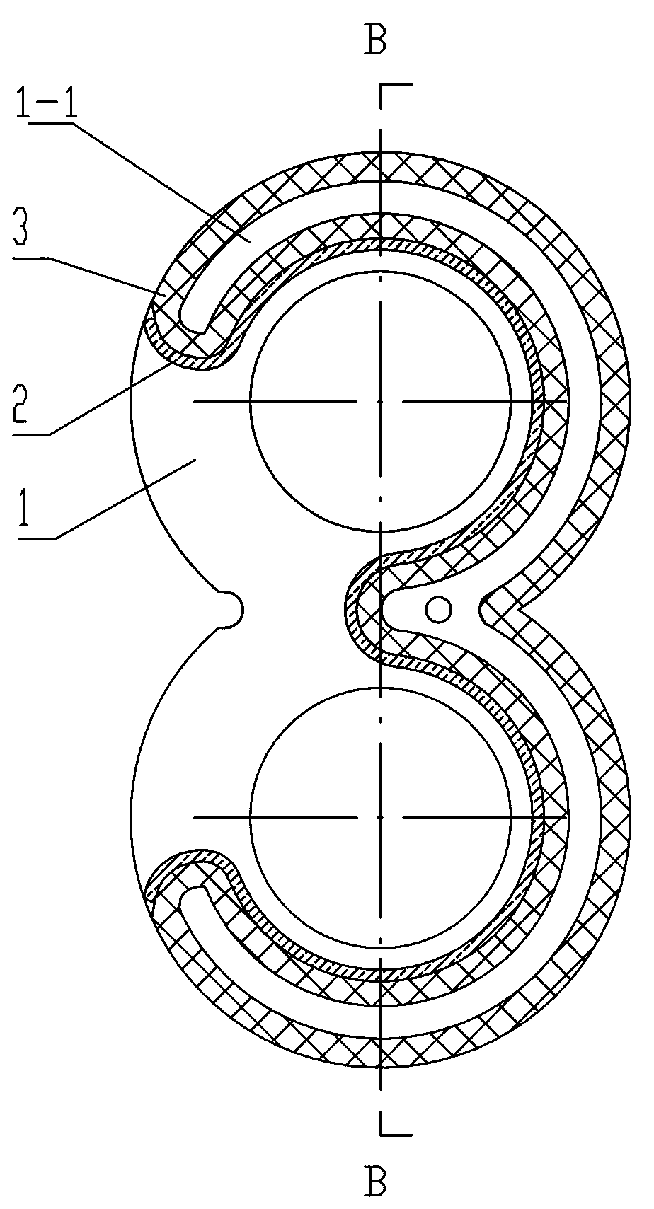
[0020] As shown in the drawings, a floating side plate of a high-pressure gear pump with a pressure plate includes a floating side plate 1 that matches the gears in the gear pump, and a “W” is made on the side of the floating side plate 1 close to the end face of the gear. Shaped balance tank a, unloading tank b communicating with balance tank a, the other side of the floating side plate 1 is made with a "W" shaped seal groove d, and there is a "W" in the "W" shaped seal groove d Shaped reinforcing rib 1-1, a through hole c is made between the "W" shaped sealing groove d and the unloading groove b, and a "W" shaped sealing ring 3 is housed in the described "W" shaped sealing groove d, The "W"-shaped sealing ring 3 is integrally set on the "W"-shaped reinforcing rib 1-1, and the thickness of the "W"-shaped reinforcing rib 1-1 is smaller than the depth of the "W"-shaped sealing groove d, so...


PUM


Abstract

The invention discloses a high-pressure gear pump floating side plate with a pressing plate, belonging to the technical field of high-pressure gear pumps. A W-shaped balance groove and an unloading groove are formed in one side of the floating side plate, a W-shaped sealing groove is formed in the other side of the floating side plate, a W-shaped reinforcing rib is arranged in the W-shaped sealing groove, a through hole is formed between the W-shaped sealing groove and the unloading groove, a W-shaped sealing ring is arranged in the W-shaped sealing groove, the thickness of the W-shaped reinforcing rib is less than the depth of the W-shaped sealing groove, a W-shaped pressing plate is arranged on the W-shaped sealing groove, and a W-shaped shallow slot is formed in the inner side of the W-shaped pressing plate. The W-shaped sealing ring can be well pressed by a region around the W-shaped shallow slot to ensure that a sealing effect of three end faces of the W-shaped sealing ring is well improved, the leakage of the floating side plate and the end face of a gear is effectively controlled, and the pressure resistance level of a hydraulic gear pump is increased.

Description

technical field [0001] The invention relates to a floating side plate of a high-pressure gear pump, belonging to the technical field of axial pressure compensation floating components of a gear hydraulic pump. Background technique [0002] At present, construction machinery products require the rated pressure of the supporting hydraulic gear oil pump to reach 25-28MPa, and some even require more than 31.5Mpa. With the intensification of the high-pressure process of hydraulic gear pumps, higher requirements are put forward for the performance of hydraulic gear pump end surface floating compensation components: under ultra-high pressure and high temperature, the floating side plate can maintain pressure balance without plastic and bending deformation; Under the impact of ultra-high pressure and unsteady flow pulsation, the sealing part of the side plate will not be damaged or deformed by impact. [0003] With the increase of the pressure level, the existing hydraulic gear pum...

Claims


Application Information

Patent Timeline
Patent Type & Authority Applications(China)
IPC IPC(8): F04C15/00
Inventor 韩永进师涛吕福春郁静
Owner XUZHOU KEYUAN HYDRAULIC
Learn More