Steam motor

A technology of steam motors and cylinder blocks, which is applied to engine components, machines/engines, internal combustion piston engines, etc. It can solve the problem that exhaust gas cannot be recycled, and achieve the effect of reasonable and compact structure, reasonable configuration, and improved efficiency

Active Publication Date: 2013-05-29
GUANGXI YUCHAI MASCH CO LTD
View PDF7 Cites 4 Cited by
  • Summary
  • Abstract
  • Description
  • Claims
  • Application Information

AI Technical Summary

Problems solved by technology

[0005] The purpose of the present invention is to disclose a steam motor, which is a part of the exhaust heat recovery device of the engine, and converts the heat energy of the exhaust gas generated by the engine into kinetic energy, so as to solve the disadvantages caused by the inability to recycle the existing exhaust gas

Method used


Image

  • Steam motor
  • Steam motor
  • Steam motor

Examples


Embodiment Construction

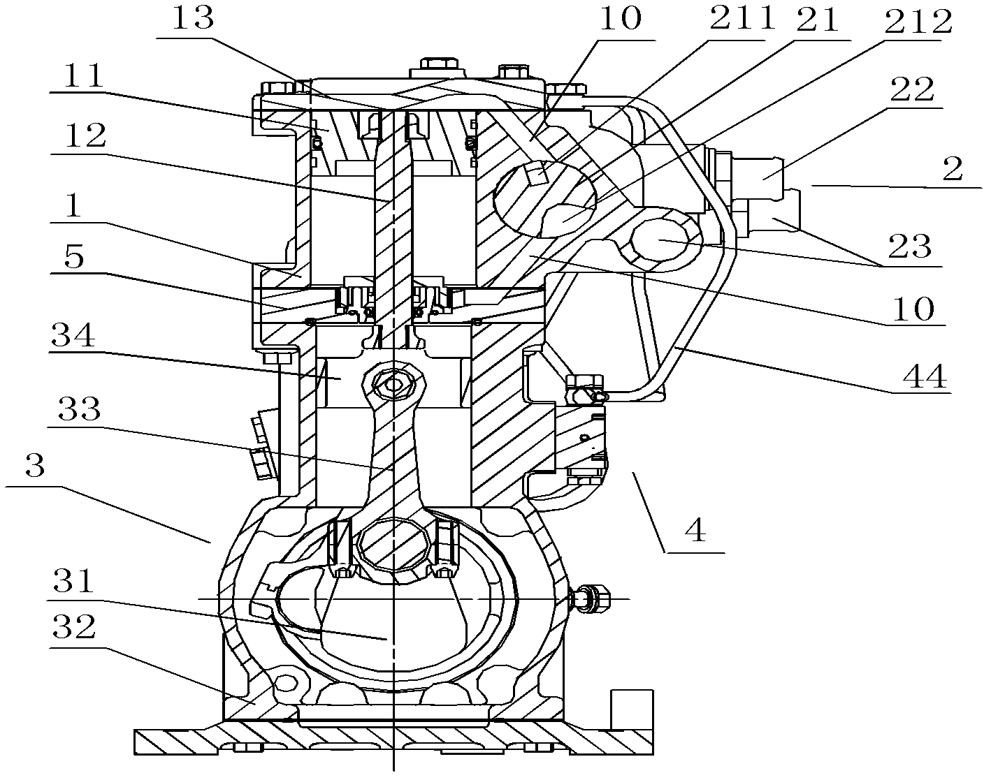
[0031] The specific implementation manners of the present invention will be described in detail below in conjunction with the accompanying drawings.

[0032] Such as Figure 1-Figure 9 As shown, the present invention discloses a steam motor, which includes a cylinder block 1, a gas distribution mechanism 2 and a power output mechanism 3. The cylinder block 1 is in the shape of a sealed cylinder, and the cylinder body of the cylinder block 1 is horizontally sealed with a piston. 11. The gas distribution mechanism 2 is provided with a gas distribution shaft 21. An air inlet groove 211 is milled in the middle of the gas distribution shaft 21, and an air outlet groove 212 is milled at both ends. The air inlet groove 211 and the air outlet groove 212 respectively correspond to the air inlet The mouth 22 is connected with the air outlet 23, the air intake groove 211 and the air outlet groove 212 can be connected with the cylinder block 1 correspondingly, the power take-off mechanism...


PUM


Abstract

The invention discloses a steam motor. The steam motor aims at solving the defect caused by the fact that the existing exhaust gas can not be recycled. The steam motor comprises a valve mechanism, a power output mechanism and an air cylinder body. The air cylinder body is in a sealing arranged cylinder body shape. A piston is installed in the air cylinder body. The piston can move in a reciprocating mode along a lengthways direction of the air cylinder body under the driving of the piston. The valve mechanism is provided with a valve shaft. An air inlet groove and an air outlet groove are formed in the valve shaft, wherein the air inlet groove and the air outlet groove are communicated with the air cylinder body. The external exhaust gas can be entered into or discharged the air cylinder body through the air inlet groove and the air outlet groove. The power output mechanism is in fit connection with the valve mechanism. The power output mechanism is provided with a bent shaft. One end of the bent shaft is in fit connection with the piston and the other end of the bent shaft is connected with an engine through a driving assembly. The discharged exhaust gas in an air exhaust pipe of the engine steam motor can heat water into steams and the steams are fed into the air cylinder body. Then, formative energy is delivered to the engine through the driving assembly so that energy conversion and recycling of exhaust gas waste heat are achieved.

Description

technical field [0001] The invention relates to a motor, in particular to a steam motor applied to a diesel engine. Background technique [0002] As we all know, the engine is generally driven by the energy released by the combustion of high-energy substances such as diesel, and the exhaust pipe of the engine will also discharge a lot of high-calorie exhaust gas accordingly. These exhaust gases can only be discharged into the atmosphere after being purified to meet the emission standards. [0003] Most of the existing exhaust gas purification devices only perform simple particle purification treatment, and ignore the heat energy contained in the exhaust gas, and discharge it directly into the atmosphere. [0004] The exhaust gas produced by the above-mentioned engines contains a large amount of heat energy. If these heat energies are discarded, the energy loss of the engine will inevitably be caused. benefit. Contents of the invention [0005] The purpose of the present ...

Claims


Application Information

Patent Timeline
IPC IPC(8): F01B23/00F01B31/10F02G5/02
CPCY02T10/166Y02T10/12
Inventor 沈琼陶泽民吴恢栋张锦刘益军
Owner GUANGXI YUCHAI MASCH CO LTD
Why Eureka
Try Eureka