Eureka AIR delivers breakthrough ideas for toughest innovation challenges, trusted by R&D personnel around the world.

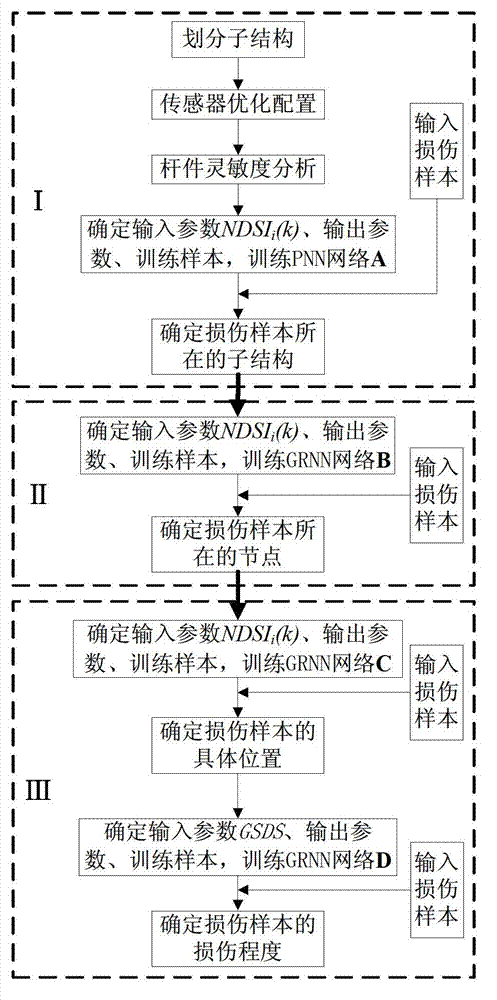
Method applicable to identifying damage to space grid structure

A technology for spatial grid and structural damage, applied in character and pattern recognition, biological neural network models, instruments, etc. The value of engineering application and the effect of enhancing practicability

Active Publication Date: 2013-05-22
江苏中闽重工科技有限公司
View PDF0 Cites 22 Cited by
  • Summary
  • Abstract
  • Description
  • Claims
  • Application Information

AI Technical Summary

Problems solved by technology

However, the existing research on structural health diagnosis is still far from the engineering application of long-span spatial structures, because the spatial grid structure has too many degrees of freedom and the actual test data that can be obtained is very limited

Method used


Image

  • Method applicable to identifying damage to space grid structure
  • Method applicable to identifying damage to space grid structure
  • Method applicable to identifying damage to space grid structure

Examples


Embodiment 1

[0037] A single-layer Kewitt reticulated shell structure is supported by three-way hinges around it, and all the rods are made of round steel pipes. The numerical model is as follows figure 2 , 3 shown. The damage of the rods in the structure is simulated by stiffness reduction, and its mass is assumed to be constant. The model modeling and modal calculations are all done by numerical simulation, that is, the finite element software ANSYS is used to complete. The following are the steps of member damage identification:

[0038] (1) Division and numbering of substructures. Notice that it is composed of 6 sectors, each sector not only has the same number and type of rods, but also has the same force characteristics, so the model can be regarded as composed of 6 substructures, numbered: 1, 2, 3, 4 , 5, 6. like figure 2 shown. Since each substructure is completely symmetrical, the first substructure is chosen as an example for discussion, such as Figure 4 As shown, the d...

Embodiment 2

[0053] The experimental model of a single-layer cylindrical reticulated shell consists of 157 nodes and 414 rods, such as Figure 5 shown. The dynamic characteristics of the first three modes were tested by sinusoidal excitation method. Taking the second substructure as an example, the structural damage is simulated by removing the rods. The test damage samples are as follows: Image 6 (black bold rod) and Table 4.

[0054] Table 4 Summary of damage samples

[0055]

[0056] (1) Division and numbering of substructures. It is noted that the model has 7 column distances in the longitudinal direction, and the number and type of members of the structure between each column distance are similar, so the test model can be regarded as composed of 7 substructures, numbered: 1, 2, 3, 4 , 5, 6, 7.

[0057] (2) Using the comprehensive ranking method of measuring point layout priority to optimize the layout of the measuring points of the reticulated shell structure, Figure 5 The ...


PUM


Abstract

The invention relates to a method for identifying damage to a large structure, in particular to a method applicable to identifying damage to a space grid structure. The method includes performing substructure-oriented damage location for the integral structure as a research object, in other words, finely dividing the space grid structure into substructures according to a formation rule of the space grid structure, and identifying possibly damaged substructures by a probabilistic neural network; and performing node-oriented damage location for each integral substructure as a research object within a reduced range, locating damage to specific bars of integral nodes as research objects and determining damage degrees of the specific bars. The method has the advantages that the method is applicable to identifying damage to large structures such as bridges, power transmission towers and high-rise buildings, and is particularly applicable to identifying damage to long-span space grid structures with numerous nodes and bars, the structure of the neural network is simplified, the nonlinear mapping ability and the damage identifying efficiency are improved, and the method has certain engineering practical value.

Description

technical field [0001] The invention relates to a damage identification method of a structure, in particular to a damage identification method of a space grid structure. Background technique [0002] Spatial grid structure is a spatial structure system composed of rods and nodes according to certain rules, mainly including grid structure, reticulated shell structure, combined grid (shell) structure and prestressed grid (shell) structure. As a local landmark building, most of them are important shelters after disasters. If an engineering accident occurs, it will cause heavy property loss at the slightest, and endanger life at the worst. It is very unfavorable to the application and development of the space structure, and the social impact is also extremely great. serious. There may be defects or damages in the built space grid structure, if these defects or damages are not maintained or strengthened in time, it will lead to engineering accidents. Literature analysis and fie...

Claims


Application Information

Patent Timeline
Patent Type & Authority Applications(China)
IPC IPC(8): G06K9/62G06N3/02
Inventor 吴金志刘才玮张毅刚
Owner 江苏中闽重工科技有限公司
Why Eureka
Eureka Blog
Learn More