Continuous feeding device for aluminum electrolysis cell and electrolysis cell with same
An aluminum electrolytic cell and electrolytic cell technology, which is applied to the continuous feeding device and field of aluminum electrolytic cell, can solve the problems of alumina concentration fluctuation, flow rate control and large measurement error, and achieve the effect of improving accuracy
- Summary
- Abstract
- Description
- Claims
- Application Information
AI Technical Summary
Problems solved by technology
Method used
Image
Examples
Embodiment 1
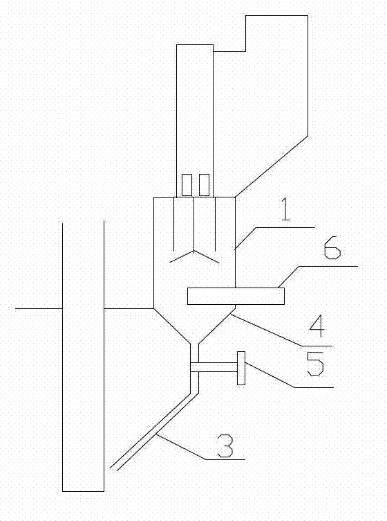
[0094] A continuous feeding device for an aluminum electrolytic cell, comprising a sleeve 1, a funnel 4 and an upper conveying pipe, the
[0095] The open end of the funnel is fixedly connected to the bottom of the sleeve 1, and the outlet end of the funnel is fixed to one end of the upper delivery pipe 3.
[0096] connect. After the funnel is installed at the bottom of the sleeve, the flow rate of the material to be lowered can be reduced, thereby realizing continuous lowering
[0097] material. The existing feeding method is a large amount of feeding at one time, and because the dissolution rate of the electrolyte to the alumina is not
[0098] Unhappy, the aluminum oxide is not completely dissolved in the electrolyte layer and sinks into the aluminum liquid, but the aluminum liquid cannot dissolve the aluminum oxide,
[0099] This causes a large amount of alumina precipitation to accumulate in the aluminum liquid layer directly below the feeding port, resulting in an inc...
Embodiment 2
[0105] On the basis of Example 1, the delivery pipe 1 can also be improved, and the upper delivery pipe is U
[0106] U-shaped delivery pipe, or V-shaped delivery pipe, there is a feed inlet in the middle of the U-shaped delivery pipe and V-shaped delivery pipe, and the drain
[0107] Open connection at the bottom of the bucket, the two outlets of the U-shaped delivery pipe and the V-shaped delivery pipe can be two discharge outlets at the same time
[0108] Unloading, not only reduces the cost, but also increases the space in the tank, U-shaped delivery pipe and V-shaped delivery pipe can also ensure
[0109] The material is unobstructed. Alumina continuously enters the electrolyte, reducing the fluctuation of alumina concentration in the electrolytic cell,
[0110] Improve current efficiency by 0.4%. At the same time, it can reduce the sedimentation at the bottom of the furnace caused by a large amount of material cutting at one time, and reduce the
[0111] The bottom p...
Embodiment 3
[0113] On the basis of implementing 1 or 2, make the following improvements, the continuous feeding device also includes
[0114] The lower delivery tube is a U-shaped delivery tube, or a V-shaped delivery tube, which is fixedly connected to one end of the upper delivery tube.
[0115] catch. If a U-shaped delivery pipe or V-shaped delivery pipe is installed at the bottom of the funnel, there are two alumina outlets, and then the U-shaped
[0116] 1 or 2 U-shaped delivery tubes and / or V-shaped delivery tubes are installed at the outlet end of the V-shaped delivery tube, i.e.
[0117] It can feed 3 or 4 feeding ports at the same time, which not only reduces the cost, but also increases the space in the tank. The U-shaped conveying
[0118] Delivery pipe and V-shaped delivery pipe can also ensure smooth discharge. Alumina continuously enters the electrolyte, reducing
[0119] Reduce the fluctuation of alumina concentration in the electrolytic cell and increase the current ef...
PUM
 Abstract
Description
Claims
Application Information
 - R&D
- Intellectual Property
- Life Sciences
- Materials
- Tech Scout
- Unparalleled Data Quality
- Higher Quality Content
- 60% Fewer Hallucinations
Browse by: Latest US Patents, China's latest patents, Technical Efficacy Thesaurus, Application Domain, Technology Topic, Popular Technical Reports.
© 2025 PatSnap. All rights reserved.Legal|Privacy policy|Modern Slavery Act Transparency Statement|Sitemap|About US| Contact US: help@patsnap.com


