
Copper pipe port machining device

A processing device and port technology, applied in the direction of metal processing equipment, forming tools, manufacturing tools, etc., can solve problems such as difficult to take out, affect production, and prone to failure in combination, so as to save parts cost, save cost, and reduce failure efficiency Effect

Inactive Publication Date: 2013-05-22
XINXIANG DONGYANG METAL PROD
View PDF6 Cites 2 Cited by
  • Summary
  • Abstract
  • Description
  • Claims
  • Application Information

AI Technical Summary

Problems solved by technology

[0003] At present, when the pipe ports in the air-conditioning pipeline parts are branched and processed in the industry, punching is used to form them (see figure 1 and figure 2 ), when working, put the product to be processed into the mandrel 9, the foot switch 6, the punch press starts, the punch press slides to drive the die handle 12 and the upper die 11 to move down, and when they move down to the lower limit, the upper die 11 and the lower die 7 match, and the stamping product is formed. At this time, the product and the mandrel 9 are tightly matched, and it is difficult to take it out. At this time, the upper mold 11 moves upward, and at the same time, the eccentric wheel 3 rotates to the position of the limit switch 4, and the solenoid valve 5 is turned on. After the valve reverses, start the cylinder 10 fixed on the connection plate 8, the cylinder works to drive the cylinder and the mandrel 9 to move backward, complete the core pulling and ejection, and take out the product easily. position, the eccentric wheel continues to rotate, leave the travel switch 4, the solenoid valve 5 is powered off and resets, the cylinder connecting plate and mandrel are reset, and are ready for the next work. The disadvantage is that the stamping equipment needs to add solenoid valves, cylinders, travel switches, etc. To set up the equipment, an air pump is also required, which is not only expensive, but also the combination of gas and electricity is prone to failure, which affects production

Method used


Image

  • Copper pipe port machining device
  • Copper pipe port machining device
  • Copper pipe port machining device

Examples


Embodiment Construction

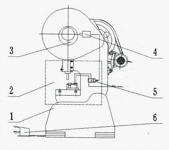
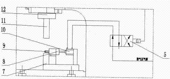
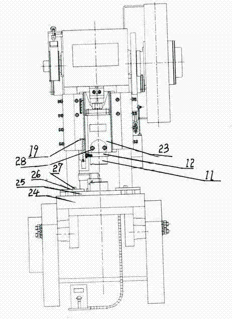
[0009] The embodiment is described in detail in conjunction with the above drawings. The present invention omits the travel switch 4, the solenoid valve 5 and the cylinder 10. The specific embodiments are as follows: the lower die 7 is assembled on the template 25, and the template 25 passes through the mold pressing plate 26 with the pressing plate screw 27 and the punching machine. The table top 24 is fixed, the upper mold 11 is assembled with the mold handle 12, the mold handle is fixed with the punch slide rail 23 through the slider mold handle fixing device 28, the cam 20 is assembled in the cam seat 13, and the cam seat is fixed on the mold handle 12 by the fixing screw 14 One end of the cam extension spring 21 and the cam are fixed by the screw 2, and the other end is fixed on the side of the punch slide rail 23 by the cam extension spring fixing screw 29. One end of the return spring 17 is connected and fixed with the return spring baffle 16, and the other end is connect...


PUM


Abstract

The invention discloses a copper pipe port machining device. The copper pipe port machining device comprises a punch press, a core rod, an upper die and a lower die. The lower die is assembled on a die plate. The upper die and a die handle are assembled. The die handle is fixed with a punch press sliding rail through a sliding block die handle fixing device. A protruding wheel is assembled in a protruding wheel seat. One ends of a protruding wheel tension spring and the protruding wheel are fixed through screws. The other end of the protruding wheel tension spring is fixed on a lateral face of the punch press sliding rail through a protruding wheel tension spring fixing screw. One ends of a reset spring and a reset spring baffle are connected and fixed. The other end of the reset spring is connected with a material returning sliding block which is arranged in a material returning sliding block groove. The core rod is arranged on a connecting plate of the material returning sliding block and the core rod. The die adopts the protruding wheel mechanical structure to loose core and retreat die and uses the tension spring and the spring to reset, and saves external equipment of an air cylinder, a magnetic valve, a travel switch and the like. The copper pipe port machining device has the advantages that not only accessories cost can be saved, but also air and electricity cost in subsequent use can be saved, after configuration is reduced, failure efficiency is reduced, and thus production efficiency is improved.

Description

[0001] Technical field: [0002] The invention relates to a copper pipe port processing device, which is especially suitable for branching processing of pipe ports in air-conditioning pipeline parts. Background technique: [0003] At present, when the pipe ports in the air-conditioning pipeline parts are branched and processed in the industry, punching is used to form them (see figure 1 with figure 2 ), when working, put the product to be processed into the mandrel 9, the foot switch 6, the punch press starts, the punch press slides to drive the die handle 12 and the upper die 11 to move down, and when they move down to the lower limit, the upper die 11 and the lower die 7 match, and the stamping product is formed. At this time, the product is closely matched with the mandrel 9, and it is difficult to take it out. At this time, the upper mold 11 moves upward, and at the same time, the eccentric wheel 3 rotates to the position of the limit switch 4, and the solenoid val...

Claims


Application Information

Patent Timeline
Patent Type & Authority Applications(China)
IPC IPC(8): B21D19/00B21D37/12
Inventor 谢任李晓曹相杰赵成刚吴雪姣
Owner XINXIANG DONGYANG METAL PROD
Learn More