Switchgear cabinet for textile machine

A technology for textile machinery and switch cabinets, applied in the field of switch cabinets, can solve problems such as affecting the function of components and contamination of components, and achieve the effect of uniform heat dissipation and cooling

Active Publication Date: 2013-05-15
SAURER GERMANY GMBH & CO KG
View PDF5 Cites 2 Cited by
  • Summary
  • Abstract
  • Description
  • Claims
  • Application Information

AI Technical Summary

Problems solved by technology

Over time, this leads to dirtying of the component and can affect the function of the component

Method used


Image

  • Switchgear cabinet for textile machine

Examples


Embodiment Construction

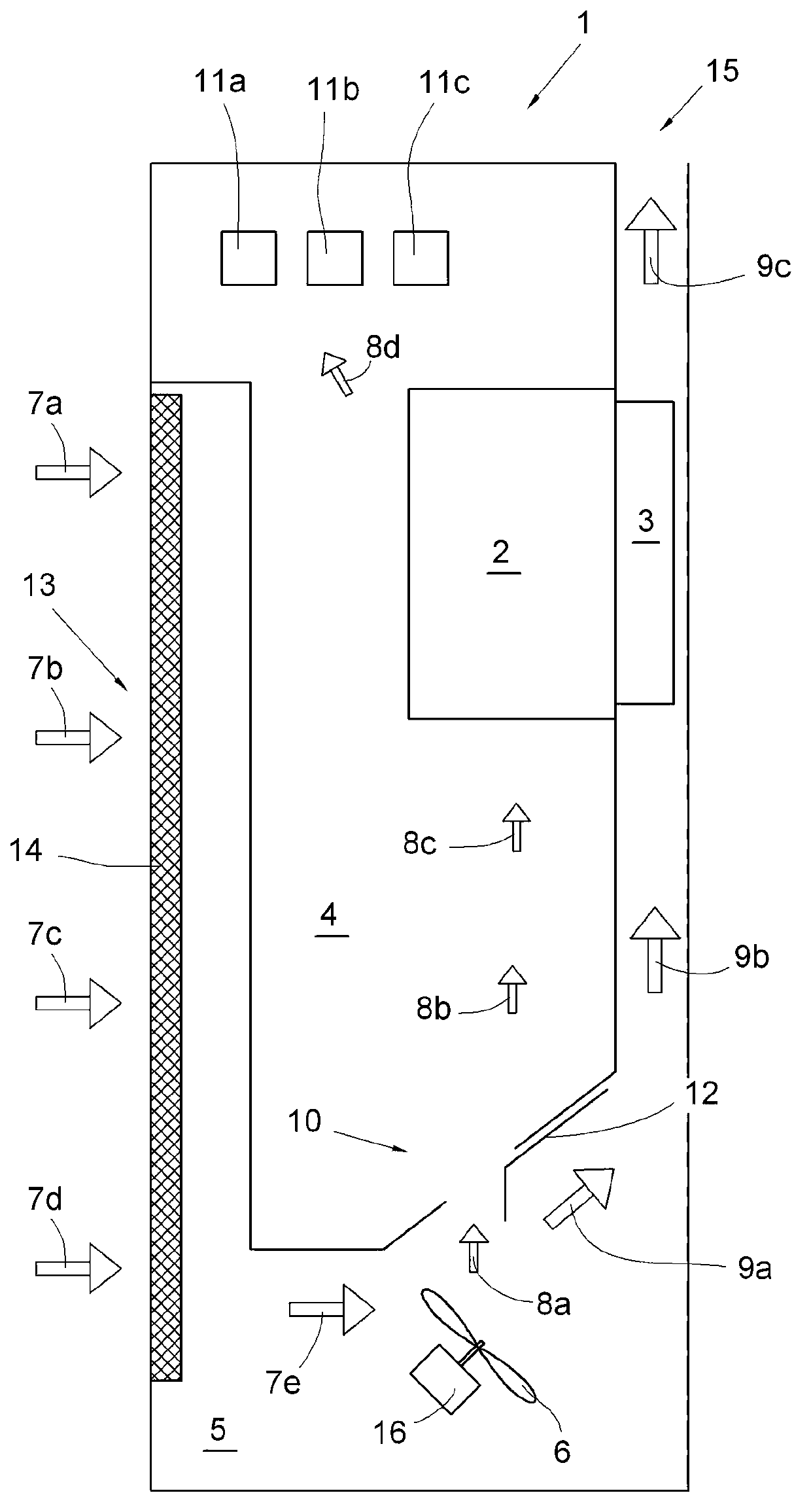
[0016] figure 1 A switchgear cabinet 1 according to the invention is shown. It has a chamber 4 in which electronic components 2 such as frequency converters are located. The electronic component 2 is thermally connected to the radiator 3 . The cooling body 3 has cooling fins and is installed in a separate chamber 5 of the switch cabinet.

[0017] Chamber 4 is substantially surrounded by chamber 5 . The chamber 5 adjoins the left vertical side of the chamber 4 on the one hand. This part of the chamber 5 also adjoins the environment. For air exchange between chamber 5 and the environment, large-area openings 13 are provided in this region. The opening 13 is provided with a filter 14 . The filter 14 should prevent flying flowers from entering the chamber 5 . The chamber 5 extends on the lower side of the chamber 4 and extends on the right vertical side of the chamber 4 . In the part of the chamber 5 which is provided on the right side of the chamber 4, a radiator 3 is ins...


PUM


Abstract

The invention relates to a switchgear cabinet (1) for a textile machine. The cabinet (1) has an electronic component (2), a heat radiating body (3) in a heat conduction connection with the electronic component (2), a first chamber (4) provided with the electronic component (2) therein, a second chamber (5) with the heat radiating body (3) therein, a fan (6) for forced air cooling of the heat radiating body (3), a first opening (10) for air exchange between the two chambers, and a second opening (11a, 11b, 11c) for air exchange between the first chamber (4) and environment. According to the switchgear cabinet, the two chambers (4, 5) are disposed in such a way that at least a part of the second chamber (5) is disposed below the first chamber (4), the first opening (10) is disposed in a lower side region of the first chamber (4), the second opening is disposed in an upper side region of the first chamber (4), and the first opening (10) and the fan (6) are disposed in such a way that, the fan (6) forces air to enter into the first chamber (4) via the first opening (10).

Description

technical field [0001] The invention relates to a switchgear for a textile machine, which has an electronic component and a heat sink connected thermally to the electronic component. The switch cabinet includes a first chamber in which the electronic component is arranged and a second chamber in which a radiator is arranged. A fan for forced air cooling of the radiator is provided in the second chamber. The switch cabinet has a first opening for exchanging air between the two chambers and a second opening for exchanging air between the first chamber and the environment. There is a third opening for drawing air from the environment into the second chamber. Background technique [0002] In the field of textile machinery, switchgear cabinets and the working mechanisms arranged therein, such as electronic components, meet special requirements compared to other applications. The air in the textile machinery workshop is doped with a lot of flying flowers. The flying flowers are...

Claims


Application Information

Patent Timeline
Patent Type & Authority Applications(China)
IPC IPC(8): H02B1/56
CPCH05K7/20136H02B1/56D01D13/00D01H13/00H05K7/20
Inventor S·艾泽勒F·马赫尼克卡尔-海因茨·麦克
Owner SAURER GERMANY GMBH & CO KG
Why Eureka
Try Eureka