
Photocatalyst ecological aluminum floor structure for carbon crystal floor heating supply system

A heating system and photocatalyst technology, applied in the field of aluminum flooring, can solve problems such as difficult to avoid heat loss, unsatisfactory heat preservation effect, long preheating time, etc., achieve good heat preservation effect, reliable connection, and improve thermal conductivity.

Inactive Publication Date: 2013-05-15
JIANGYIN WANYUAN TEXTILE MACHINERY MFG
View PDF0 Cites 7 Cited by
  • Summary
  • Abstract
  • Description
  • Claims
  • Application Information

AI Technical Summary

Problems solved by technology

The carbon crystal floor heating system with this structure mainly has the following defects: (1) Since there is still a cement leveling layer between the carbon crystal heating plate and the floor, the preheating time is long, the heat preservation effect is not ideal, and the energy consumption is large; (2) There is a layer of insulation layer under the carbon crystal heating plate, but it is difficult to avoid a certain amount of heat loss

Method used


Image

  • Photocatalyst ecological aluminum floor structure for carbon crystal floor heating supply system
  • Photocatalyst ecological aluminum floor structure for carbon crystal floor heating supply system
  • Photocatalyst ecological aluminum floor structure for carbon crystal floor heating supply system

Examples


Embodiment Construction

[0024] The carbon crystal heating plate is made of polymer nano-semiconductor material - carbon crystal as the main material, adding far-infrared emitter, and epoxy resin, high temperature and high pressure. After the product is energized, under the excitation of the electric field, the carbon molecules The clusters produce "Brownian motion" and collide with each other, friction generates heat energy, and generates a large amount of infrared radiation. 29% conduction heat and nearly 71% far-infrared radiant heat are generated within tens of seconds of electrification, (the electric energy conversion rate is close to 100% after testing), and the heat energy is transferred to the covering on the surface of the carbon crystal electric heating material. After 2-4 minutes, the heating element It reaches a thermal equilibrium with the insulation material, and radiates directly to the heating space at a constant temperature.

[0025] When manufacturing the above-mentioned carbon crys...


PUM

PropertyMeasurementUnit
Thicknessaaaaaaaaaa

Abstract

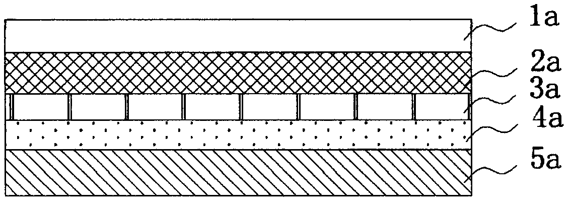
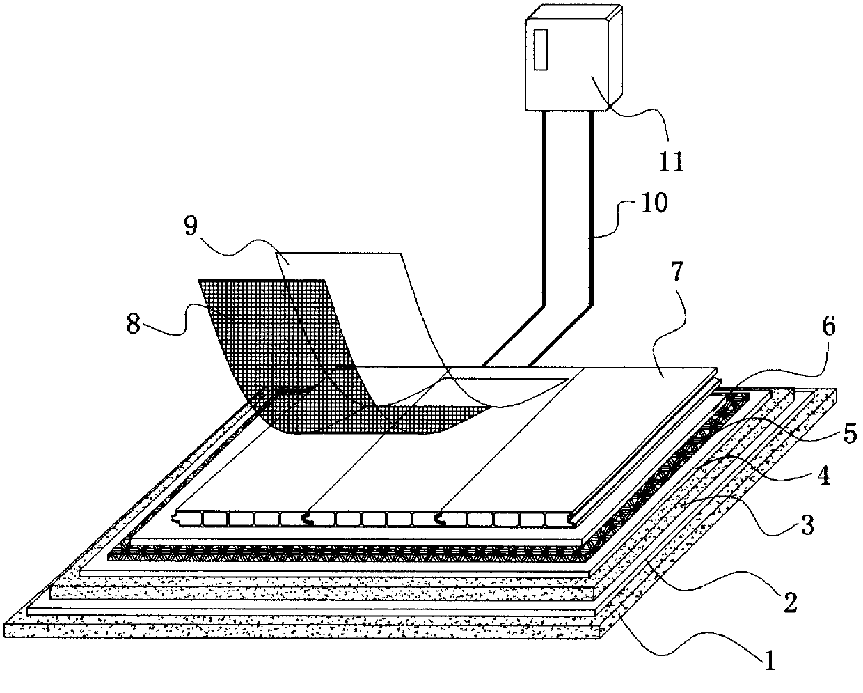
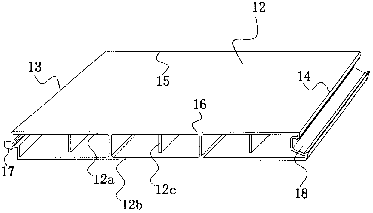
The invention relates to a photocatalyst ecological aluminum floor structure for a carbon crystal floor heating supply system. The photocatalyst ecological aluminum floor structure is placed on a cement terrace, and is characterized in that a first dampproof insulating layer, a heat preserving layer, a reflecting film, a carbon crystal heating board, a second dampproof insulating layer, an aluminum floor and a photocatalyst coating are sequentially paved on the cement terrace. The aluminum floor is formed by connecting a plurality of rectangular floor blocks, the left side edges and the right side edges of the floor blocks are first side edges and second side edges, wherein the first side edges and the second side edges are mutually parallel, and the first side edges and the second side edges are respectively provided with first connection structures and second connection structures. The upper side edges and the lower side edges of the floor blocks are third side edges and fourth side edges, and the third side edges and the fourth side edges are mutually parallel and straight sides. The floor blocks with adjacent left sides and right sides are connected through the first connection structures and the second connection structures. The photocatalyst ecological aluminum floor structure can prevent heat from spreading to grounds and forces the heat to be transmitted towards indoor space, is good in heat preserving effect, reduces thermal loss and improves heat conduction efficiency. The photocatalyst coating is adopted and the floor structure can have the functions of antibacterium, air purification and easy cleaning.

Description

technical field [0001] The invention relates to an aluminum floor for a floor heating heating device, in particular to a photocatalyst ecological aluminum floor structure for a carbon crystal (hereinafter referred to as "carbon crystal") floor heating system. Background technique [0002] The development of people from the most primitive heating by warming fires to the current heating with air conditioners, radiators, water heaters, heating cables, etc. reflects the improvement of people's living standards and the advancement of science and technology. However, the existing heating methods inevitably have high energy consumption, high pollution, and high waste. Compared with the traditional heating system, carbon crystal floor heating can reduce carbon by 90%, and save energy by 40%. It will lead the transformation of energy saving and environmental protection in the heating system, and essentially reverse the disadvantages of existing heating in energy consumption and charg...

Claims


Application Information

Patent Timeline
IPC IPC(8): F24D13/02F24D19/00E04F15/06E04F15/18
CPCY02B30/00
Inventor 卞文君
Owner JIANGYIN WANYUAN TEXTILE MACHINERY MFG
Learn More