Cooling system control method and device

A technology of cooling system and control method, applied in pump control, liquid variable capacity machinery, reduction of greenhouse gases, etc. The effect of preventing pump overflow, increasing system resistance, and reducing capacity

Active Publication Date: 2015-08-12
MITSUBISHI POWER LTD
View PDF7 Cites 0 Cited by
  • Summary
  • Abstract
  • Description
  • Claims
  • Application Information

AI Technical Summary

Problems solved by technology

At this time, if the flow of the pump exceeds the maximum possible flow point, it may cause damage to the pump or motor due to excessive flow
[0017] Therefore, in order to prevent the overflow of the pump, Patent Document 1 controls the rotation speed of the pump, but this method is difficult to adjust the flow rate of cooling water correctly, and it is difficult to maintain the cooling system at a desired temperature
In addition, Patent Document 2 is a structure provided with an excess flow control valve, but in this structure, a time lag occurs from detection of the flow rate of the pump to control of the opening of the excess flow control valve.
In particular, if it is a large valve, it takes time to open and close, so it is unavoidable to continue the pump's excessive flow state during this period
[0018] On the other hand, as a method of reducing the starting torque of the pump, in Patent Document 3, the discharge stop valve of the pump is half-opened to start the pump, but the discharge stop valve of the conventional pump is opened and closed manually, for example, , in an emergency like a power outage, it is difficult for the operator to properly open and close the discharge shut-off valve
[0019] In addition, even in any of the above-mentioned prior art, there is no specific control method that can solve the problem when the pump is started, that is, solve the problem of pump overflow and increased starting torque. Appropriate operation control technology when the number of pumps is less than normal operation

Method used


Image

  • Cooling system control method and device
  • Cooling system control method and device
  • Cooling system control method and device

Examples


Embodiment Construction

[0070] Embodiments of the present invention will be described below with reference to the drawings. However, the dimensions, materials, shapes, and relative arrangements of components described in this embodiment are not limited to specific descriptions, nor are they intended to limit the scope of the present invention thereto, but are merely illustrative examples.

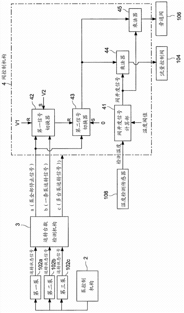
[0071] figure 1 It is a configuration diagram showing the equipment configuration of the cooling system and its control device according to the embodiment of the present invention.

[0072] refer to figure 1 , first, a cooling system to which an embodiment of the present invention is applied will be described. This cooling system 100 is set up for cooling the auxiliary equipment of the nuclear power plant, mainly possesses: the circulation line 101 that makes the cooling water circulate by the closed loop; With respect to the multiple pumps 102a, 102b, 102c that are connected in parallel with the circulation l...


PUM


Abstract

The invention provides a control method and device for a cooling system, when a pump for the cooling system and with less normal operation is started, starting torque of pump is reduced, and over-current flow of the pump is prevented. The cooling system is provided with: a circulating line for circulation of cooling materials for cooling an auxiliary device in a nuclear power plant, a plurality of pumps in parallel relative to the circulating line; and a flow control valve disposed at an exhaust side downstream of the plurality of pumps and adjusting flow of the cooling materials. The control method comprises: a valve fully-closed control step, wherein the number of pumps in operation is detected, under the condition that stop of a plurality of the pumps is detected, a valve control signal for controlling full-closing of the flow control valve is output; a first pump starting step, wherein in a state that the flow control valve is fully-closed, less operation pumps than normal are started; and a first open valve control step, wherein after the first pump starting step, a valve control signal for controlling the flow control valve below a limiting openness is output, and the limiting opening is set to be smaller than an upper limit of the flow control valve in normal operation.

Description

technical field [0001] The invention relates to a control method and a control device of a cooling system for cooling auxiliary equipment of an atomic power plant. Background technique [0002] Generally, a nuclear power plant is provided with a cooling system for the purpose of cooling auxiliary equipment. Auxiliary equipment mentioned here is equipment other than nuclear reactors, such as turbines or generators. The cooling system directly or indirectly cools auxiliary equipment, and cools lubricating oil supplied to bearings of a turbine, cools coolant supplied to a generator, or cools other auxiliary equipment. For example, in a pressurized water reactor, a high-temperature gas reactor, or a high-speed breeder reactor, a primary cooling system that removes heat generated by the nuclear reactor and a secondary cooling system that generates steam using the heat recovered from the primary cooling system are independently installed. secondary cooling system. [0003] like...

Claims


Application Information

Patent Timeline
Patent Type & Authority Patents(China)
IPC IPC(8): F04B49/06G21D3/08
CPCY02E30/40Y02E30/00
Inventor 今治义典河户希美
Owner MITSUBISHI POWER LTD
Why Eureka
Try Eureka