Radial magnetic field coreless permanent-magnet wind driven generator

A wind turbine, radial magnetic field technology, applied to synchronous motors with stationary armatures and rotating magnets, synchronous machine parts, shapes/styles/structures of winding conductors, etc. , small output power and other problems, to achieve the effect of expanding the scope of application of wind speed, reducing starting torque, and improving torque ripple

Active Publication Date: 2011-03-30
ZHENGZHOU SENYUAN NEW ENERGY TECH
View PDF1 Cites 2 Cited by
  • Summary
  • Abstract
  • Description
  • Claims
  • Application Information

AI Technical Summary

Problems solved by technology

Generally, the rated wind speed of the above-mentioned permanent magnet generator (that is, the output rated power speed) is relatively high, usually in the range of 10-12m / s, and the diameter of the fan blade is too large. In the low wind speed area where the air volume is insufficient, the output power is small. Can't even generate electricity, can't make rational use of wind energy
[0003] The patent number is 200820059414.1, and in the utility model patent titled "A Permanent Magnet Generator", although a permanent magnet generator with no iron core for wind power generation is given, the upper and lower end covers, upper and lower permanent magnet yokes, permanent The magnet and the coil are closely connected, the air gap is small, but it is difficult to guarantee the machining accuracy, the process is difficult, and it does not play a big role in solving the starting torque, and the implementation effect is not good; in addition, the structure is complex and difficult to manufacture
[0004] Patent No. 87206678, in the utility model patent titled "Disc Ironless AC Permanent Magnet Generator", although a permanent magnet generator with ironless core for wind power generation is also given, but the structure is complicated, and the coil It is too thick, the air gap is large, the magnetic field strength is small, and the output power is small. At the same time, its rated speed is too high, which is not conducive to starting in the breeze, and it also does not solve the problem that the permanent magnet wind turbine can run efficiently in the breeze

Method used


Image

  • Radial magnetic field coreless permanent-magnet wind driven generator
  • Radial magnetic field coreless permanent-magnet wind driven generator
  • Radial magnetic field coreless permanent-magnet wind driven generator

Examples


Embodiment 1

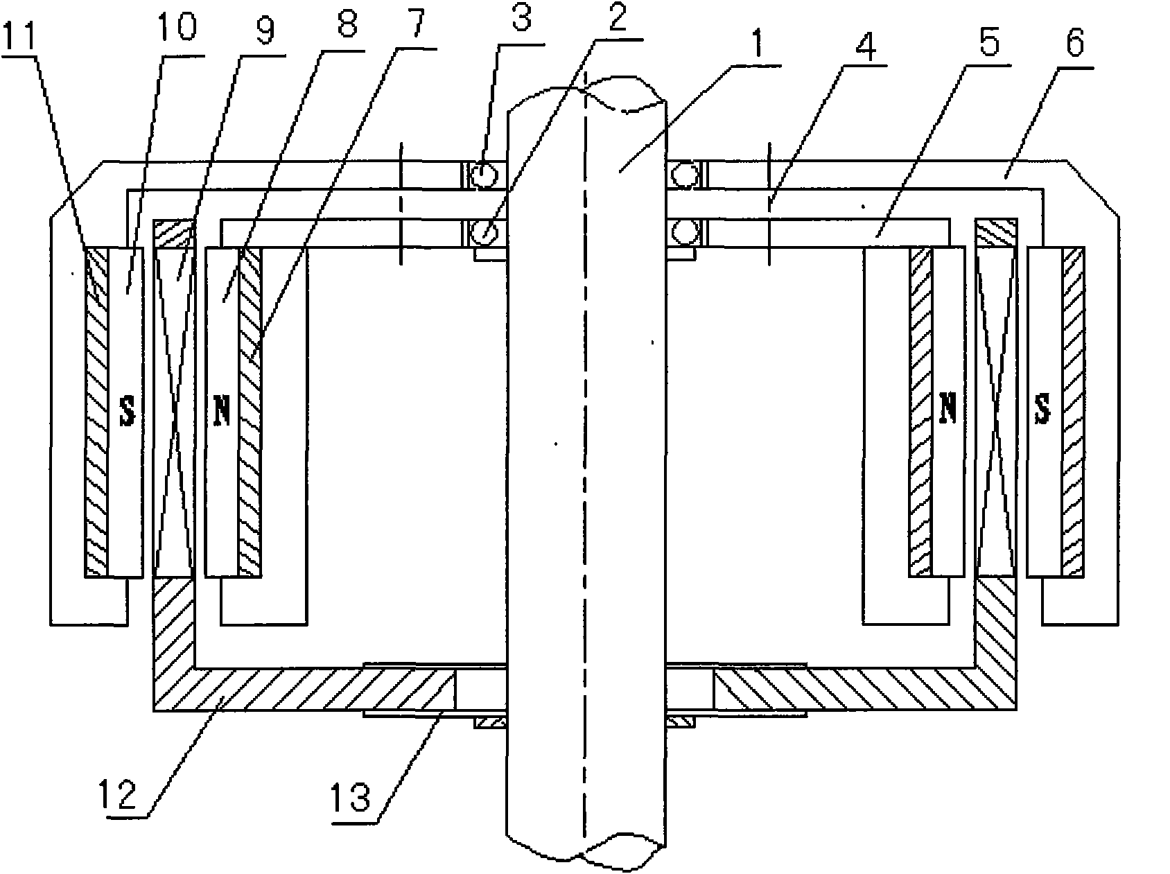
[0024] like figure 1 As shown, the present invention includes a rotor inner cylinder 5 , a rotor outer cylinder 6 and a stator cylinder 12 arranged coaxially. Among them, the rotor inner cylinder 5 and the rotor outer cylinder 6 form a double-cylinder rotor structure, and the cylinders made of aluminum alloy are the best embodiment. The rotor inner cylinder 5 is connected to the main shaft 1 through the rotor inner bearing 2, the rotor outer cylinder 6 is connected to the main shaft 1 through the rotor outer bearing 3, and the rotor inner bearing 2 and the rotor outer bearing 3 are tightly fitted and pressed on the main shaft 1 . In addition, the rotor inner cylinder 5 and the rotor outer cylinder 6 are integrally connected by bolts 4, so that the rotor inner cylinder 5 and the rotor outer cylinder 6 can rotate synchronously. Moreover, the nozzle directions of the rotor inner cylinder 5 and the rotor outer cylinder 6 are in the same direction, while the nozzle direction of t...

Embodiment 2

[0030] The difference between this embodiment and Embodiment 1 is that in this embodiment, 24 pieces of three-phase inner magnetic steel 8 are evenly distributed along the circumference on the cylinder wall of the rotor inner cylinder 5, and on the cylinder wall of the rotor outer cylinder 6 24 pieces of three-phase outer magnetic steel 10 are evenly distributed along the circumference, and 18 wire coils 9 are evenly distributed along the circumference on the cylinder wall of the stator cylinder 12 . The polarity distribution of the inner magnetic steel 8 and the outer magnetic steel 10 is the same as that of the first embodiment.

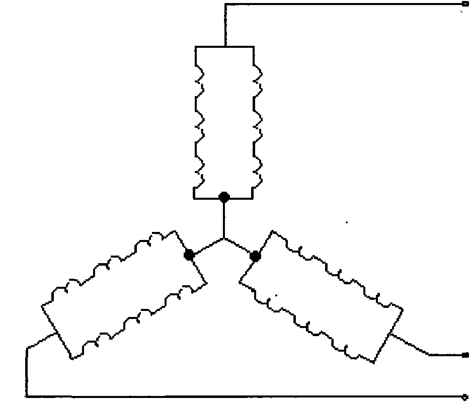
[0031] In addition, if image 3 As shown, the connection mode of the coil 9 is a three-phase Y junction, three series and two parallel 3S2P, that is, the coil 9 has a three-phase Y-shaped structure as a whole, and each phase is composed of two coil groups connected in parallel, each coil Groups are formed from three coils connected in series.

[...

Embodiment 3

[0034] like Figure 4 As shown, the difference between this embodiment and Embodiment 1 and Embodiment 2 is that in this embodiment, the connection mode of the wire coil 9 is a three-phase Y junction, six strings and one parallel 6S1P, that is, the wire coil 9 as a whole is a three-phase Y Shaped structure, and each phase is formed by six coils connected in series.

[0035] Other technical characteristics are identical with embodiment 1.


PUM


Abstract

The invention discloses a radial magnetic field coreless permanent-magnet wind driven generator, comprising a rotor inside cylinder, a rotor outside cylinder and a stator cylinder which are arranged coaxially; wherein, the rotor inside cylinder and the rotor outside cylinder are connected into a whole and are connected with a main shaft by a bearing, and the opening directions of the rotor inside cylinder and the rotor outside cylinder are consistent, the opening direction of the stator cylinder is opposite to that of a rotor cylinder, and the wall of the stator cylinder is arranged between the rotor inside cylinder and the rotor outside cylinder, inner magnetic steel is uniformly distributed at the periphery on the wall of the rotor inside cylinder, outer magnetic steel is uniformly distributed at the periphery on the wall of the rotor outer cylinder, the polarity of the uniformly distributed inner magnetic steel and the outer magnetic steel is changed in an alternating way, and the polarity of the opposite inner magnetic steel and the outer magnetic steel is opposite, and wire coils are uniformly distributed on the wall of the stator cylinder. In the invention, starting torque is effectively reduced, so as to solve the problem that the dynamo is difficult to start under the condition of breeze.

Description

technical field [0001] The invention relates to a permanent magnet generator, in particular to a permanent magnet wind generator with a radial magnetic field without an iron core. Background technique [0002] According to the configuration of the magnets in the rotor, small AC permanent magnet generators generally have various types such as radial magnetic field type, tangential magnetic field type, hybrid internal permanent magnet structure and surface permanent magnet structure. Existing permanent magnet generators for small wind power generation usually adopt a horizontal shaft structure with an iron core, such as the Guangzhou Hongying HY-400 with relatively advanced technology and the FD-500 permanent magnet wind generator in Jiangsu Huaian. Wait. The stator windings of these permanent magnet generators are embedded in the iron core slot according to certain rules. Because of the small air gap, the suction force between the magnet and the iron core is large, the start...

Claims


Application Information

Patent Timeline
IPC IPC(8): H02K21/12H02K21/02H02K3/28
Inventor 邓隐北楚金甫周保臣楚光辉
Owner ZHENGZHOU SENYUAN NEW ENERGY TECH
Why Eureka
Try Eureka