
Reinforcing steel bar movement conveying mechanism of welding machine of mesh

A technology for moving conveying and welding mesh machines, applied in the field of mesh welding machines, can solve the problems of low production efficiency, long adjustment time, inability to meet market demands, etc., and achieve the effect of high production efficiency

Active Publication Date: 2013-05-15
TJK MACHINERY TIANJIN
View PDF8 Cites 32 Cited by
  • Summary
  • Abstract
  • Description
  • Claims
  • Application Information

AI Technical Summary

Problems solved by technology

[0003] The steel bar conveying mechanism of the prior art welded mesh machine has the following defects: the longitudinal bar spacing of the welded mesh machine is set before inputting the steel bars, so the grid spacing of the continuously welded mesh sheets is the same; The incoming line block of the machine is also set in advance. When changing the diameter of the steel bar, the incoming line block of different specifications must be adjusted before welding. In this way, the continuous production of meshes with different steel bar diameters and grid spacings cannot be guaranteed.
When the specifications need to be changed, the adjustment time needs to be longer, resulting in high production costs and low production efficiency
Defects that cannot meet market demand

Method used


Image

  • Reinforcing steel bar movement conveying mechanism of welding machine of mesh
  • Reinforcing steel bar movement conveying mechanism of welding machine of mesh
  • Reinforcing steel bar movement conveying mechanism of welding machine of mesh

Examples


Embodiment Construction

[0012] Embodiments of the present invention will be further described below in conjunction with the accompanying drawings.

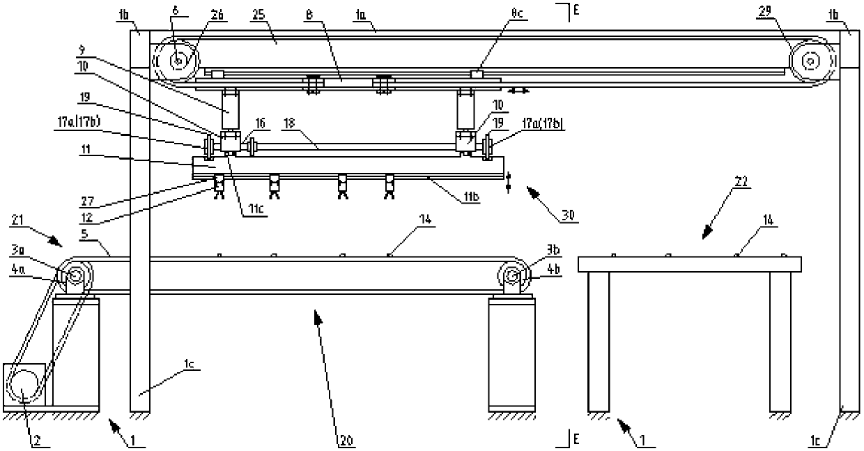
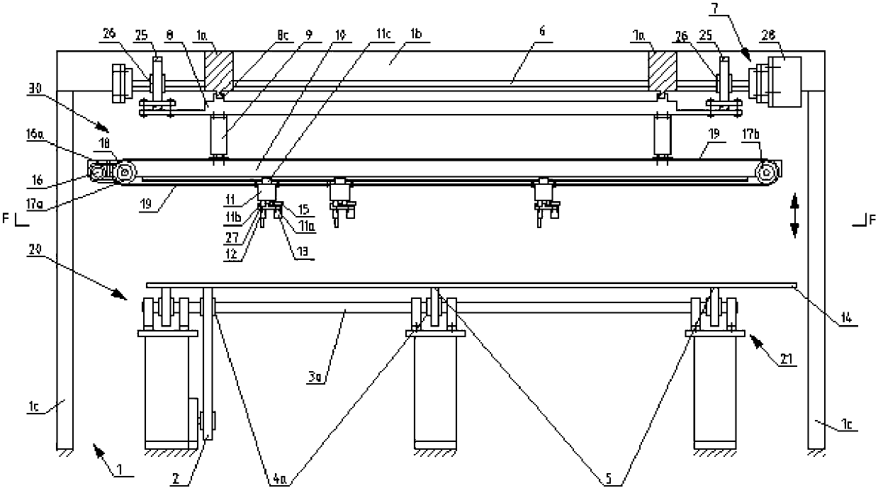
[0013] As shown in the figure, the present invention provides a steel bar moving and conveying mechanism of a welding mesh machine. The steel bar moving and conveying mechanism includes: a frame 1, a steel bar moving input mechanism 20 arranged at the bottom of the frame 1; The steel bar movement output mechanism 30; The mesh welding workbench 22 located at the side of the steel bar movement input mechanism 20. The frame 1 includes four vertical columns 1c, two symmetrical upper beams 1b are welded on the top of the columns 1c, and two upper longitudinal beams 1a are welded and fixed between the two upper beams 1b; the frame 1 also includes support The support of mesh welding workbench 22.

[0014] The steel bar movement input mechanism 20 includes: a plurality of translation conveying devices 21 arranged at intervals and juxtaposed, and the conveying s...


PUM


Abstract

The invention discloses a reinforcing steel bar movement conveying mechanism of a welding machine of mesh. The reinforcing steel bar conveying mechanism comprises a machine frame, a reinforcing steel bar movement input mechanism, a reinforcing steel bar movement output mechanism and a mesh welding work table. The reinforcing steel bar movement input mechanism comprises a plurality of horizontal conveying devices, and the reinforcing steel bar movement output mechanism comprises a plurality of longitudinal regulating beams, wherein a plurality of clamping mechanical arms are arranged at the bottom of each longitudinal regulating beam. The upper portion of each longitudinal regulating beam is provided with a transverse sliding block which is matched with the bottom of each transverse regulating beam in a sliding mode and is connected with the bottom of each transverse regulating beam in a hung mode, each transverse regulating beam is connected with a lifting mechanism connected with the lower portion of one conveying movement beam, and the upper portion of each conveying movement beam is hung on an upper longitudinal beam in a sliding match mode and is connected with a conveying driving mechanism which is arranged on an upper transverse beam of the machine frame. The reinforcing steel bar movement conveying mechanism has the advantages that the diameter and the length of each reinforcing steer bar on each horizontal conveying device can be regulated freely, reinforcing steer bar grids having different diameters and different intervals can be welded on the same mesh, market requirements are met, and production efficiency is high.

Description

technical field [0001] The invention relates to a wire mesh welding machine, in particular to a steel bar moving conveying mechanism of the wire mesh welding machine. Background technique [0002] The wire mesh welding machine in the prior art cuts the wire rod steel bars into horizontal bars and longitudinal bars after straightening, and transports the transverse bars and longitudinal bars to the horizontal bar storage device and the longitudinal bar storage device respectively, and then from the horizontal bar storage device and the longitudinal bar storage device The longitudinal rib storage device is respectively output to the mesh welding table according to the specified spacing, and the transverse rib and longitudinal rib are welded by the welding electrode to form a mesh. [0003] The steel bar conveying mechanism of the prior art welded mesh machine has the following defects: the longitudinal bar spacing of the welded mesh machine is set before inputting the steel ba...

Claims


Application Information

Patent Timeline
IPC IPC(8): B65G25/02B65G47/90
CPCB21F23/005B21F27/10B21F27/20
Inventor 陈振东
Owner TJK MACHINERY TIANJIN
Learn More