Manual punching die

A punching die, punching die technology, applied in punching tools, metal processing, metal processing equipment and other directions, can solve the problems of inconvenient disassembly, low production efficiency, poor processing quality, etc., and achieves processing time and labor saving, simple structure, and manufacturing. handy effect

Inactive Publication Date: 2013-05-15
HENAN BENMA
View PDF0 Cites 0 Cited by
  • Summary
  • Abstract
  • Description
  • Claims
  • Application Information

AI Technical Summary

Problems solved by technology

[0002] In the fields of machining and other fields, when processing holes on thinner copper plates, aluminum plates, or thinner non-metallic materials, due to the thinner workpiece material, if the conventional drilling process is performed, the drilled holes often appear out of round and the workpiece positioning The defects of difficult clamping and inconvenient disassembly, low production efficiency and poor processing quality, especially for workpieces with small dimensions, a small number of holes in a single part, and small batches, if large stamping equipment is invested, It is very uneconomical, and the cost is high, the processing is difficult, and it is not conducive to normal production

Method used


Image

  • Manual punching die
  • Manual punching die
  • Manual punching die

Examples


Embodiment Construction

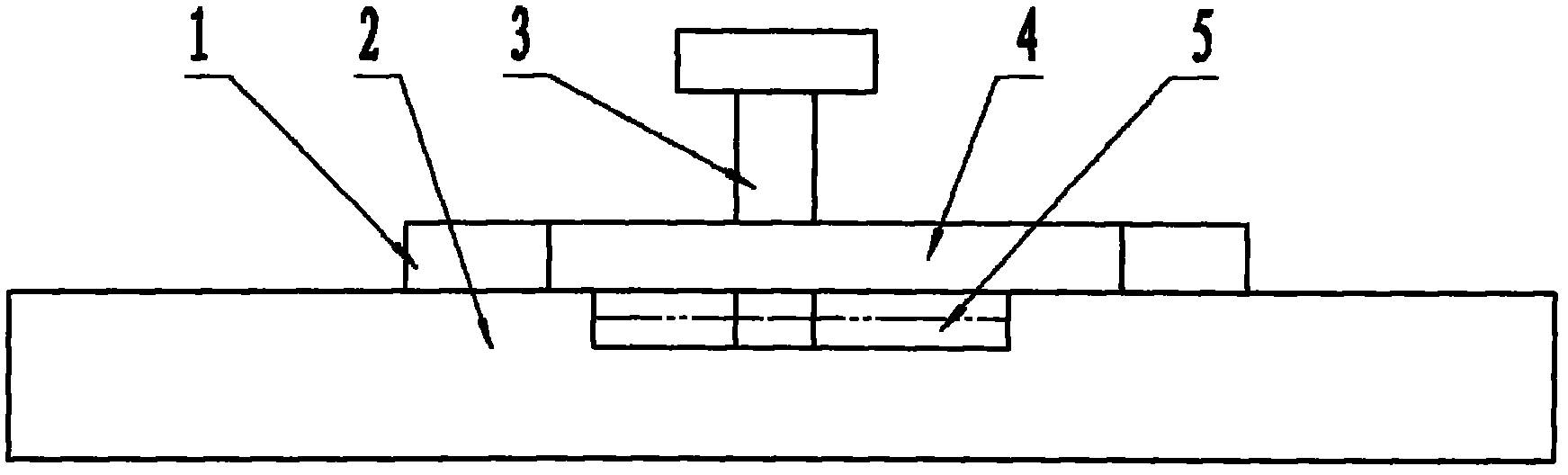
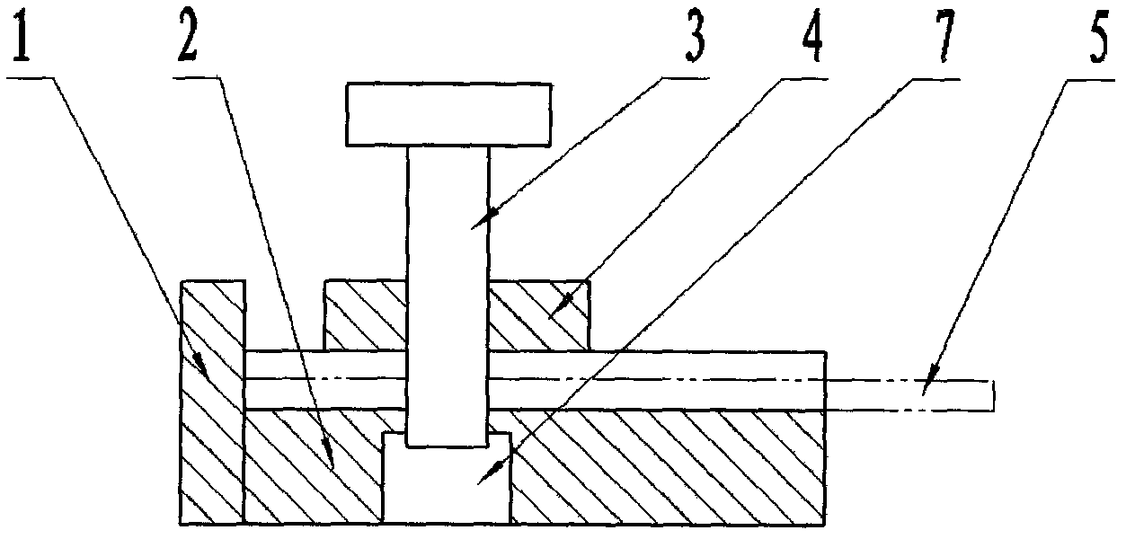
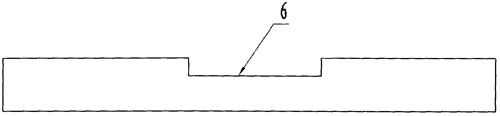
[0013] as attached figure 1 - attached Figure 4 As shown, a manual punching die is composed of a rear baffle, a lower die base, a punch, an upper punching plate, a workpiece, etc., and is characterized in that: before punching, the workpiece 5 is inserted into the limiting groove 6 of the lower die base 2 , relying on the limit groove 6 and the rear baffle plate 1 to limit the position without clamping, the punch 3 is inserted into the upper die hole of the upper punch plate 4, and the top of the punch 3 is lightly tapped with a hand hammer, and the punch 3 moves down into the anti-sinking In the die hole 7 under the head, the hole required by the design has just been punched on the workpiece 5.

[0014] The material of the workpiece 5 is a thinner copper plate, aluminum plate or thinner non-metallic material. The punch 3 does not punch down by mechanical power, but punches down after being lightly tapped with a hammer. big occasion.

[0015] The lower die base 2 is proces...


PUM


Abstract

A manual punching die is mainly composed of parts including a rear baffle, a lower punching die base, an upper punching die plate, a punch, a workpiece and the like. The manual punching die is characterized in that the rear baffle is welded together with the lower punching die base, the lower punching die base is provide with a limiting groove, the workpiece is located through the limiting groove formed in the lower punching die base and the rear baffle, the workpiece is only located but not clamped, so that the workpiece can be quickly replaced. A reversed countersunk head lower punching die hole is formed in the lower punching die base, wherein the upper end of the reversed countersunk head lower punching die hole is matched with the punch in size, the hole at the lower end is large, so that blanking of flushing cinder and plug-out of the punch are convenient. The upper punching die plate is welded on the upper plane of the lower punching die base, and a punching die hole in the upper punching die plate facilitates guide of the punch and location rectification of the punch hole in the workpiece. The manual punching die has the advantages of being simple in structure, convenient to manufacture, time-saving and labor saving in machining, low in cost, capable of being widely used in the field of machining, and particularly suitable for materials such as copper boards and aluminum boards or nonmetal, wherein the copper boards, the aluminum boards or the nonmetal are thin in material, and the manual punching die is suitable for occasions of small-number machining holes of a single part and small-batch machining.

Description

Technical field: [0001] The invention belongs to the field of mechanical processing, in particular to a manual punching die. Background technique: [0002] In the fields of machining and other fields, when processing holes on thinner copper plates, aluminum plates, or thinner non-metallic materials, due to the thinner workpiece material, if the conventional drilling process is performed, the drilled holes often appear out of round and the workpiece positioning The defects of difficult clamping and inconvenient disassembly, low production efficiency and poor processing quality, especially for workpieces with small dimensions, a small number of holes in a single part, and small batches, if large stamping equipment is invested, Very uneconomical, and cost is higher, and processing difficulty is big, is unfavorable for normal production. Invention content: [0003] The purpose of the present invention is to provide a manual punching die to overcome the shortcomings in the pri...

Claims


Application Information

Patent Timeline
Patent Type & Authority Applications(China)
IPC IPC(8): B26F1/14B21D28/34
Inventor 楚金甫王红军
Owner HENAN BENMA
Why Eureka
Try Eureka