An overflow device and fluidization equipment with the device

An overflow device and fluidization technology, which is applied in the field of overflow device of fluidized bed and multi-stage fluidized bed, can solve problems such as overflow pipe instability and overflow pipe failure to work normally

Active Publication Date: 2016-08-10
ENN SCI & TECH DEV
View PDF6 Cites 0 Cited by
  • Summary
  • Abstract
  • Description
  • Claims
  • Application Information

AI Technical Summary

Problems solved by technology

However, the commonly used overflow pipe is a straight pipe type at present, but this kind of overflow pipe is prone to instability of the "material seal" in the overflow pipe due to the pressure fluctuation at the lower end. When the material seal is momentarily lower than the critical material seal, it is easy to cause "Throttling" so that the overflow pipe forms a "bolt" and cannot work normally

Method used


Image

  • An overflow device and fluidization equipment with the device

Examples


Embodiment Construction

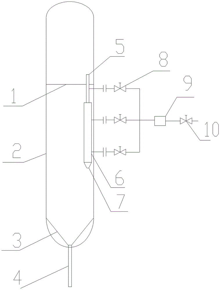
[0029] like figure 1 As shown, in one embodiment of the present invention, the overflow device of the present invention can be installed in the internal overflow multi-stage fluidization equipment. The multi-stage fluidization equipment includes a horizontal distribution plate 1 , a gasifier body 2 , a conical distribution plate 3 and a central pipe 4 .

[0030] The overflow device of the present invention is a vertical overflow device used in fluidization equipment, and the overflow device is a hollow tubular body in a longitudinal shape, and the hollow tubular body has an upper inlet (as shown in reference numeral 5 ) and the lower end outlet (as shown by reference numeral 7), wherein: on a length above the lower end outlet 7 of the overflow device, the internal cross section of the overflow device is larger than the internal cross section of the upper end inlet 5, And larger than the inner cross section of the outlet 7 at the lower end, thus, the length of the overflow dev...


PUM

PropertyMeasurementUnit
angleaaaaaaaaaa
lengthaaaaaaaaaa
diameteraaaaaaaaaa

Abstract

The invention discloses a vertical overflow device for fluidization equipment. The overflow device is a hollow tubular body with an elongated shape; the hollow tubular body is provided with an upper inlet and a lower outlet; and for a section above the lower outlet of the overflow device, internal cross section of the overflow device is larger than that of the upper inlet and that of the lower outlet, so that the section forms an internal cross section enlargement section. The invention also discloses fluidization equipment with the overflow device. The invention solves the problems of a fluidization dead zone caused by large diameter of an overflow pipe, and shutdown of the overflow pipe caused by material seal fluctuation generated by bubble fluctuation at an overflow outlet. The invention also provides a solution scheme for the condition of overflow pipe shutdown.

Description

technical field [0001] The invention relates to an overflow device, in particular to an overflow device for a fluidized bed. The invention also relates to fluidized equipment, such as a multi-stage fluidized bed, provided with said overflow device. Background technique [0002] The multi-stage fluidized bed is to install horizontal distribution plates and overflow pipes inside the fluidized bed, and to establish multiple dense phase areas of material particles along the axial direction of the fluidized bed to form multiple independent fluidized beds connected in series. The multi-stage fluidized bed facilitates the establishment of concentration and temperature gradients, improves the driving force for gas phase conversion, and facilitates the control of the processing characteristics of solid material particles according to different concentration and temperature characteristics. The solid material particles in the fluidized bed flow from the upper fluidized bed to the nex...

Claims


Application Information

Patent Timeline
Patent Type & Authority Patents(China)
IPC IPC(8): B01J8/26B01J8/28C01B31/08B01D53/83B01J38/30C12M1/00F26B25/00C01B32/30C01B32/318
CPCY02P20/584
Inventor 崔鑫祖静茹孙志强李克忠毛燕东毕继诚
Owner ENN SCI & TECH DEV
Why Eureka
Try Eureka