
Golf club head

A golf club head and club head technology, which is applied to golf balls, golf clubs, rackets, etc., can solve problems such as low rigidity, difficulty in obtaining, and strength problems

Active Publication Date: 2013-05-15
YAMAHA CORP
View PDF4 Cites 1 Cited by
  • Summary
  • Abstract
  • Description
  • Claims
  • Application Information

AI Technical Summary

Problems solved by technology

[0006] However, in the golf club head described in Patent Document 1, a low-rigidity and easy-to-bend crown portion is generally formed inside a region called the crown surface. Only this portion is relatively easy to deform, and it is difficult to obtain a side surface of the club head. There is still room for improvement in terms of sufficient deformation for the deformation of the state brought in by the side
In addition, due to the use of resin materials, there is a problem in strength along with making it low rigidity

Method used


Image

  • Golf club head
  • Golf club head
  • Golf club head

Examples


Embodiment 1

[0029] [Club Specifications]

[0030] Playing order No. 1 club (No. 1 wood, lie angle: 64 degrees)

[0031] The area of ​​the top surface forming part of the club head 13150mm 2

[0032] The area of ​​the sole forming part is 14277mm 2

[0033] The area of ​​the crown forming part / the area of ​​the sole forming part 92%

[0034] Head top plate thickness 0.6mm (accounting for 78% of the head surface, the remaining 22% plate thickness is 0.75mm)

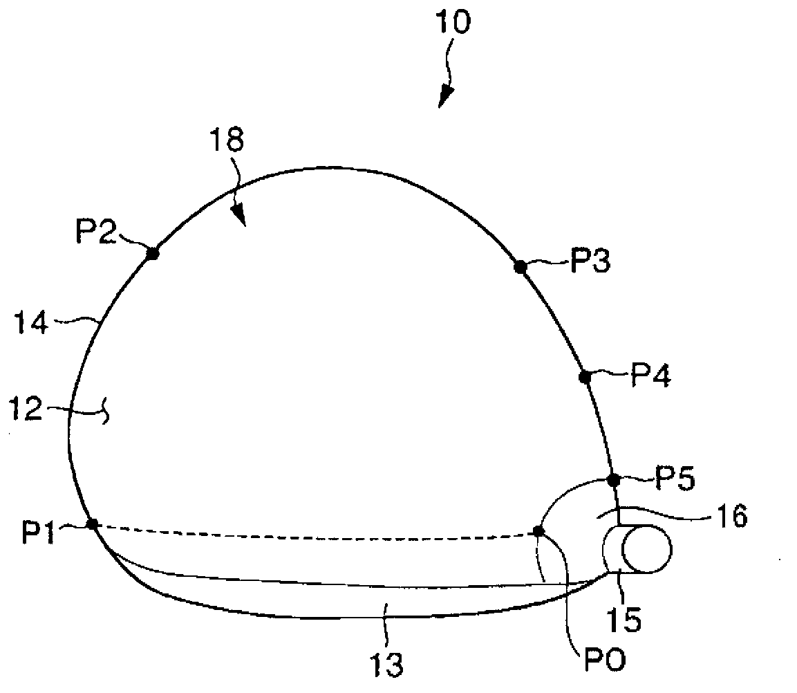
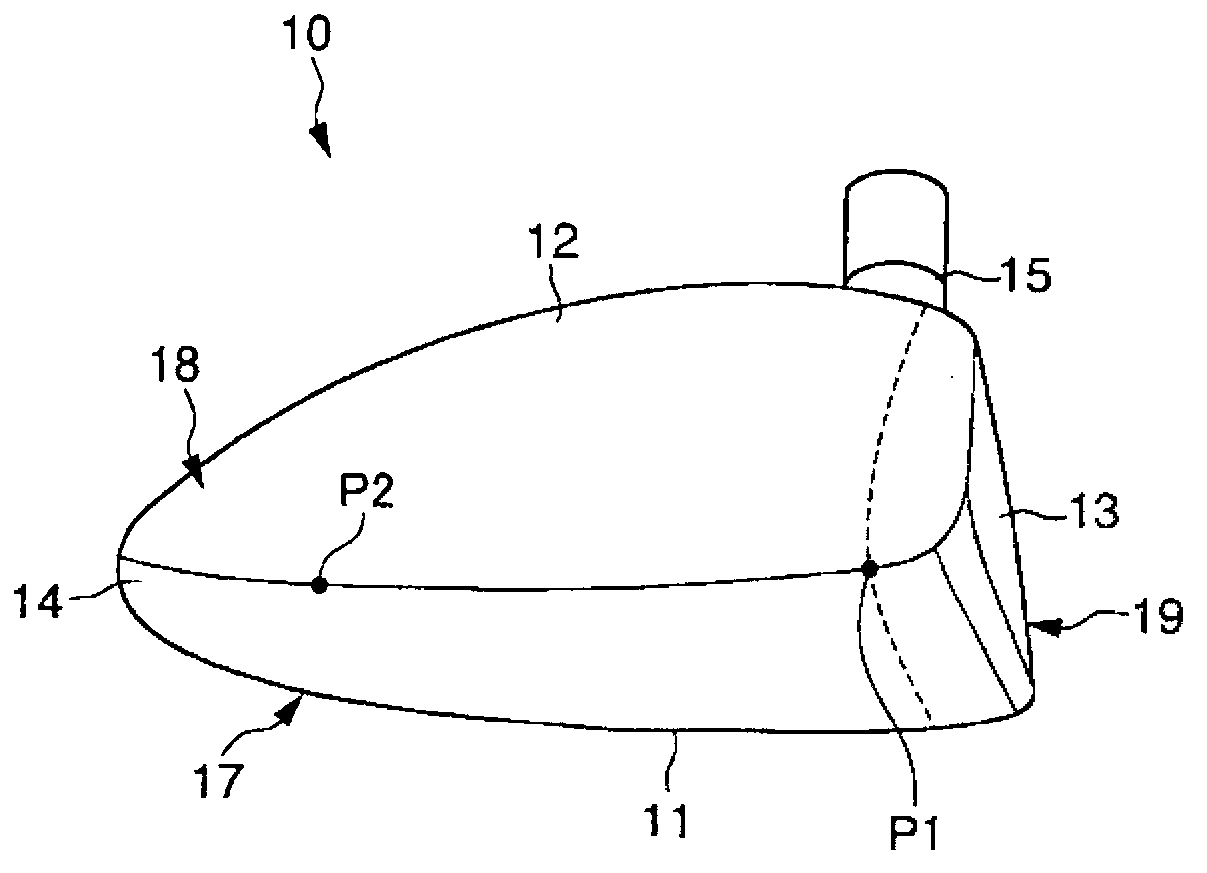
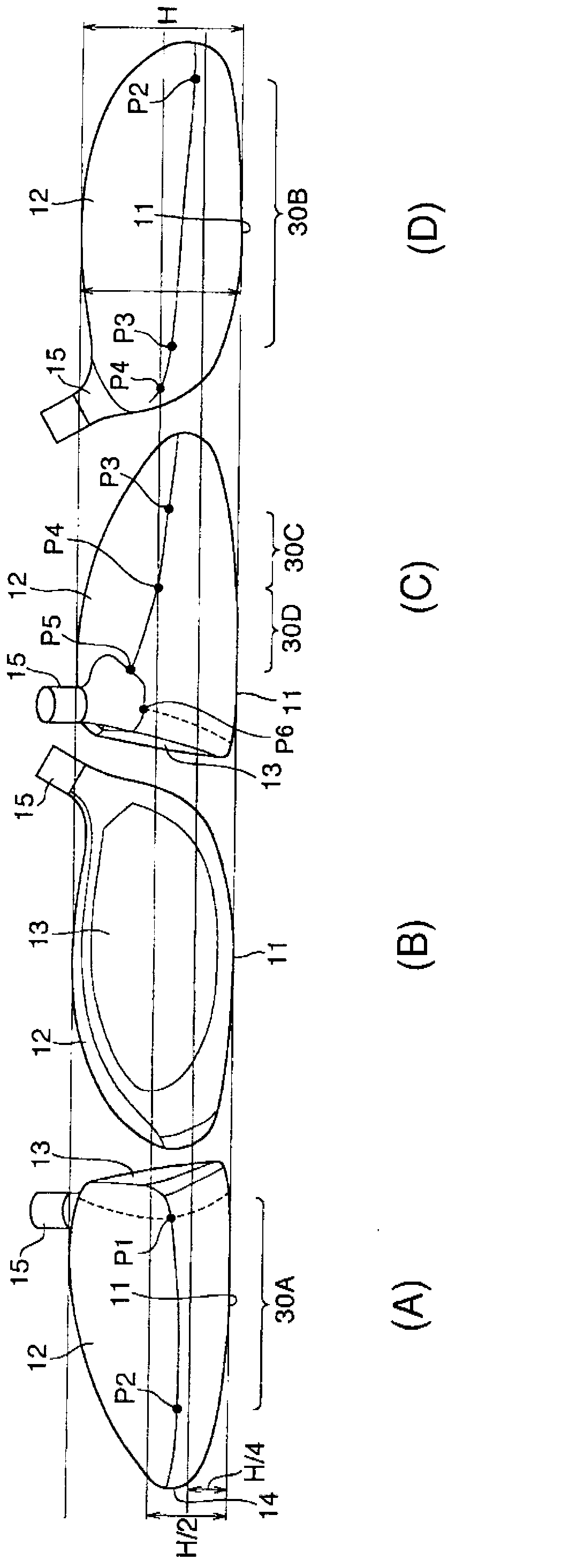
[0035] The joint position of the top surface forming part and the sole surface forming part ( image 3 The joint position 30A to 30C is in the range of 1 / 4 to 1 / 2)

[0036] Sole forming part plate thickness 0.75mm

[0037] Clubhead loft 11 degrees

[0038] Head Weight 179.5g

[0039] Head volume 460cc

[0040] Shaft for 2010inpresXClassic No. 1 wood (softness R)

[0041] Grip for 2010inpresXClassic 1-wood

[0042] Club Length 46.25"

[0043] Total club weight 275g

[0044] Balance C3

[0045] The golf club described above ...


PUM

PropertyMeasurementUnit
Plate thicknessaaaaaaaaaa

Abstract

The invention discloses a golf club head, wherein based on the elastic deformation of the top surface of the club head, the hitting angle is ensured to be larger than the inclination of the club while the backspin momentum applied on a golf ball is reduced so as to prolong the flight distance of the golf ball. The golf club head is provided with a bottom surface forming part (17) used for forming the bottom surface (11) of the golf club head, a top surface forming part (18) used for forming the top surface (12) of the golf club head, and engagement parts (30A, 30B and 30C) formed from the top side (P1), the back side to the central heel side (P4) of the golf club head so as to be positioned within the 1 / 4-1 / 2 range of the height of the golf club head. In this way, the central part of the top surface (12) of the golf club head is bent in an expansion manner, so that the inclination of the ball surface is increased temporarily and the hitting angle is increased temporarily.

Description

technical field [0001] The present invention relates to a golf club head, and more specifically, to a golf club head capable of reducing (optimizing) the amount of backspin of the ball when hitting the ball, increasing the launch angle, and extending the flight distance. Background technique [0002] In order for the golf ball to fly farther, it is not only necessary to increase the speed of the club head, but also to have a square club face and use the sweet spot to catch the ball, and the amount of backspin and launch angle of the ball are also factors for extending the flight distance. [0003] For example, if the amount of backspin is too large, the ball will become a bouncing (rapidly rising) trajectory, and after reaching the highest point, it will drop rapidly, causing a greater loss of distance. The same is true for the launch angle. If the launch angle is too large, the ball will reach the highest point in a short time and then drop rapidly, resulting in a greater l...

Claims


Application Information

Patent Timeline
IPC IPC(8): A63B53/04A63B102/32
CPCA63B53/04A63B53/0408A63B53/0437A63B2102/32
Inventor 土田厚志角田幸介柴健一郎
Owner YAMAHA CORP
Learn More