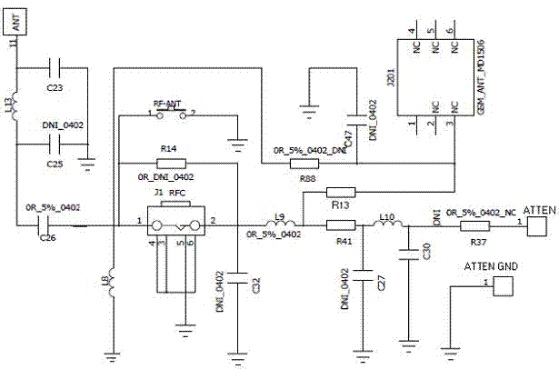
Radio frequency antenna matching design circuit
A technology for designing circuits and radio frequency antennas, applied in the field of antenna circuits, can solve problems affecting wireless terminals, inconsistency, and increase design costs, so as to achieve the effect of reducing costs and quickly responding to market demand
- Summary
- Abstract
- Description
- Claims
- Application Information
AI Technical Summary
Problems solved by technology
Method used
Image
Examples
Embodiment 1
[0034] Such as figure 1 shown.
[0035] The antenna matching design circuit is mainly composed of an antenna signal input matching circuit, a patch antenna matching circuit and a radio frequency choke circuit connected to the antenna signal input matching circuit at the same time, the radio frequency choke circuit is connected with a PF antenna matching circuit, and the The PF antenna matching circuit is connected with the patch antenna matching circuit.
[0036] The antenna signal input matching circuit is mainly composed of an antenna signal input ANT, an inductor L13, a capacitor C26, and an inductor L8 connected in series in sequence. Both ends of the inductor L13 are connected with capacitors C23 and C25 connected in parallel to the ground, and the capacitor C26 is close to the inductor L8. One end is connected with patch antenna matching circuit and radio frequency choke circuit.
[0037] The radio frequency choke circuit is mainly composed of a grounded radio frequenc...
PUM
 Abstract
Description
Claims
Application Information
 - R&D Engineer
- R&D Manager
- IP Professional
- Industry Leading Data Capabilities
- Powerful AI technology
- Patent DNA Extraction
Browse by: Latest US Patents, China's latest patents, Technical Efficacy Thesaurus, Application Domain, Technology Topic, Popular Technical Reports.
© 2024 PatSnap. All rights reserved.Legal|Privacy policy|Modern Slavery Act Transparency Statement|Sitemap|About US| Contact US: help@patsnap.com


