
Patsnap Eureka
For R&D, Patsnap Eureka makes reading and utilizing patents & technical documents easy.
Patsnap Eureka AIR
Designed for self-driven R&D workflows. Generate viable solutions, solve complex R&D challenges, empower your innovation with AI.

Patsnap Eureka Materials
Designed for material experts only. Revolutionize your material R&D, from search, analyze, to developing new materials.

TechResearch
Generate reliable direction feasibility study reports for your R&D in just a few steps.

TechSeek
Discover and master advanced knowledge NOW. Basics, ideas, possibilities, all at once.

TechMind
As an expert in R&D Theories, TechMind can generates customized viable solutions instantly.

TechRisk
Analyze your overall solution with one click, know your potential R&D risks in advance.

TechMonitor
Get weekly tech updates, stay abreast of the latest tech innovations and key insights.
Switching converter double pulse frequency modulation V<2> type control method and device thereof
A pulse frequency modulation, switching converter technology, applied in the direction of output power conversion devices, electrical components, etc., can solve the problems affecting the stability of the converter, and achieve good system stability, small transient overshoot, and improved transient performance. The effect of state performance
- Summary
- Abstract
- Description
- Claims
- Application Information
AI Technical Summary
Problems solved by technology
Method used
Image

Examples
Embodiment 1
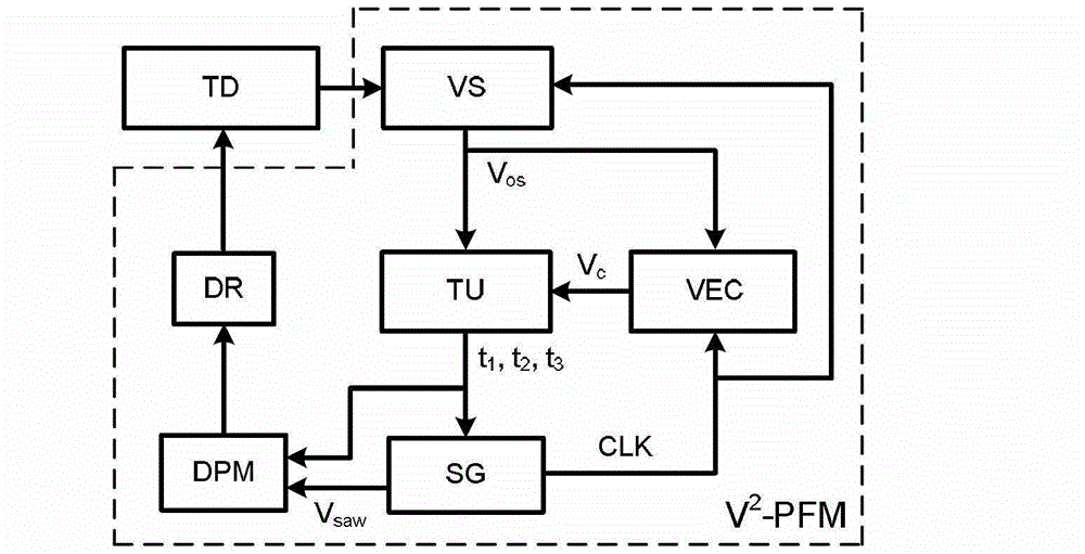
[0031] figure 1 Shown, a specific implementation of the present invention is: switching converter dual-edge pulse frequency modulation V 2 Type control method and its device V 2 PFM, its V 2 - The PFM device is mainly composed of a voltage detection circuit VS, a controlled error compensator VEC, a time operation unit TU, a variable frequency sawtooth wave generator SG, a double edge pulse modulator DPM and a driving circuit DR. The voltage detection circuit VS is used to obtain the output voltage value V os , the controlled error compensator VEC is used to generate the control voltage V c , the time operation unit TU is used to generate three periods of time t 1 , t 2 , t 3 , the variable frequency sawtooth wave generator SG is used to generate variable frequency sawtooth wave V saw and the sampling pulse signal CLK, the double-edge pulse modulator DPM is used to generate t 1 , t 2 , t 3 The timing control pulse signal controls the turn-on and turn-off of the switch...
Embodiment 2
[0042] Figure 7 It shows that the converter TD controlled in this example is a single-transistor forward converter, and the control device of the switching tube S adopts V 2 PFM. Figure 8 In Embodiment 2 of the present invention, output voltage, control voltage V c , time t 1 , time t 2 , time t 3 , a schematic diagram of the relationship between the sampling pulse signal CLK and the driving signal.
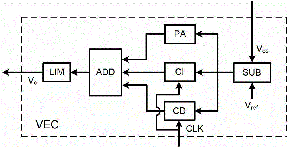
[0043] The specific working process and principle are: Figure 7 , Figure 8 It shows that the switching tube is turned off at any starting moment of the sampling pulse signal CLK, and at the same time, the voltage detection circuit VS detects the output voltage of the converter TD to obtain the output voltage value V os , and with reference voltage V ref It is sent to the controlled error compensator VEC to generate the control voltage V c . preset a constant off-time T OFF , t 1 , t 3 Same as off time and satisfy t 1 +t 3 =T OFF , then t 2 is the turn-on time...
Embodiment 3
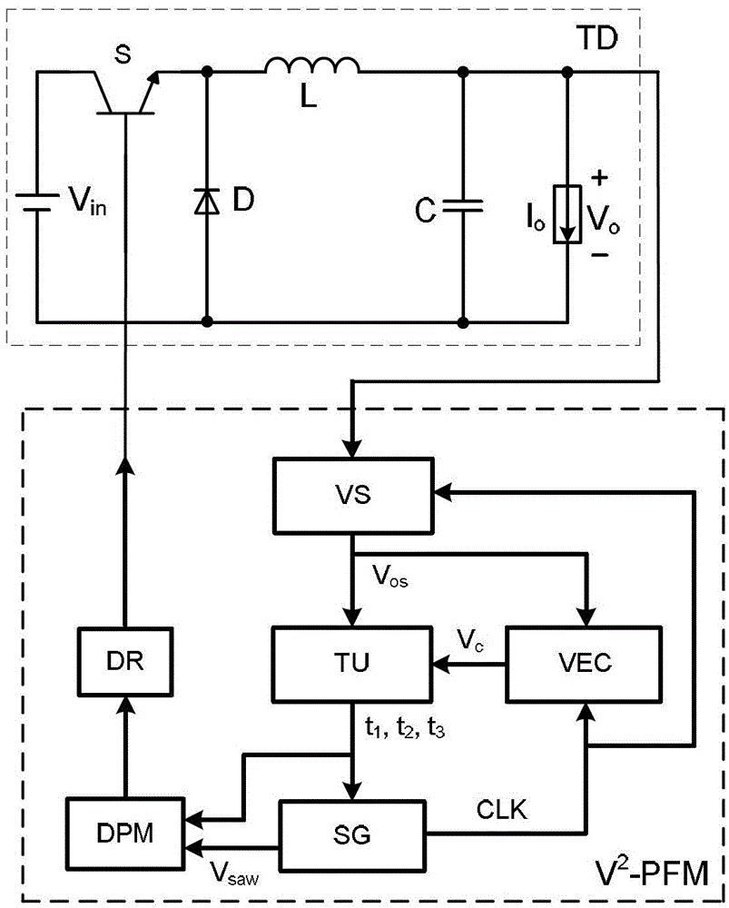
[0046] Such as Figure 9 As shown, this example is basically the same as Embodiment 1, the difference is: the converter TD controlled by this example is Buck 2 converter.
[0047] The inventive method can also be used for double-tube forward converter, Cuk converter, Zeta converter, push-pull converter, push-pull forward converter, half-bridge converter except being applicable to the switching converter in the above embodiment. , full-bridge converter and other circuit topologies.
PUM
 Abstract
Description
Claims
Application Information
 - R&D Engineer
- R&D Manager
- IP Professional
- Industry Leading Data Capabilities
- Powerful AI technology
- Patent DNA Extraction
Browse by: Latest US Patents, China's latest patents, Technical Efficacy Thesaurus, Application Domain, Technology Topic, Popular Technical Reports.
© 2024 PatSnap. All rights reserved.Legal|Privacy policy|Modern Slavery Act Transparency Statement|Sitemap|About US| Contact US: help@patsnap.com