
Package structure and manufacturing method for the same

A packaging structure and manufacturing method technology, applied in the direction of electrical components, electrical solid devices, circuits, etc., can solve the problems of shrinking packaging volume, expanding spacing, internal damage of chips and substrates, etc.

Inactive Publication Date: 2013-05-08
WALSIN LIHWA
View PDF3 Cites 9 Cited by
  • Summary
  • Abstract
  • Description
  • Claims
  • Application Information

AI Technical Summary

Problems solved by technology

[0003] However, when the chip is bonded to the substrate, whether it is conductive adhesive or alloy solder, these adhesive materials have the property of thermal expansion and contraction, so when the temperature rises, the volume of the adhesive material will expand , so that there are holes inside the adhesive material, so that the adhesive material not only cannot reduce the distance between the chip and the substrate to reduce the packaging volume, but is more likely to expand the distance due to the appearance of holes, which in turn causes alignment deviation during die bonding.
Furthermore, when metal solder is used in the die-bonding process, the temperature of the alloy is high when it reaches the molten state, which makes the chip and the substrate easy to cause internal damage due to high temperature, and the high temperature of the chip and the substrate will cause stress changes, and such a phenomenon It is not conducive to subsequent processing, so it is necessary to control the welding temperature and welding time

Method used

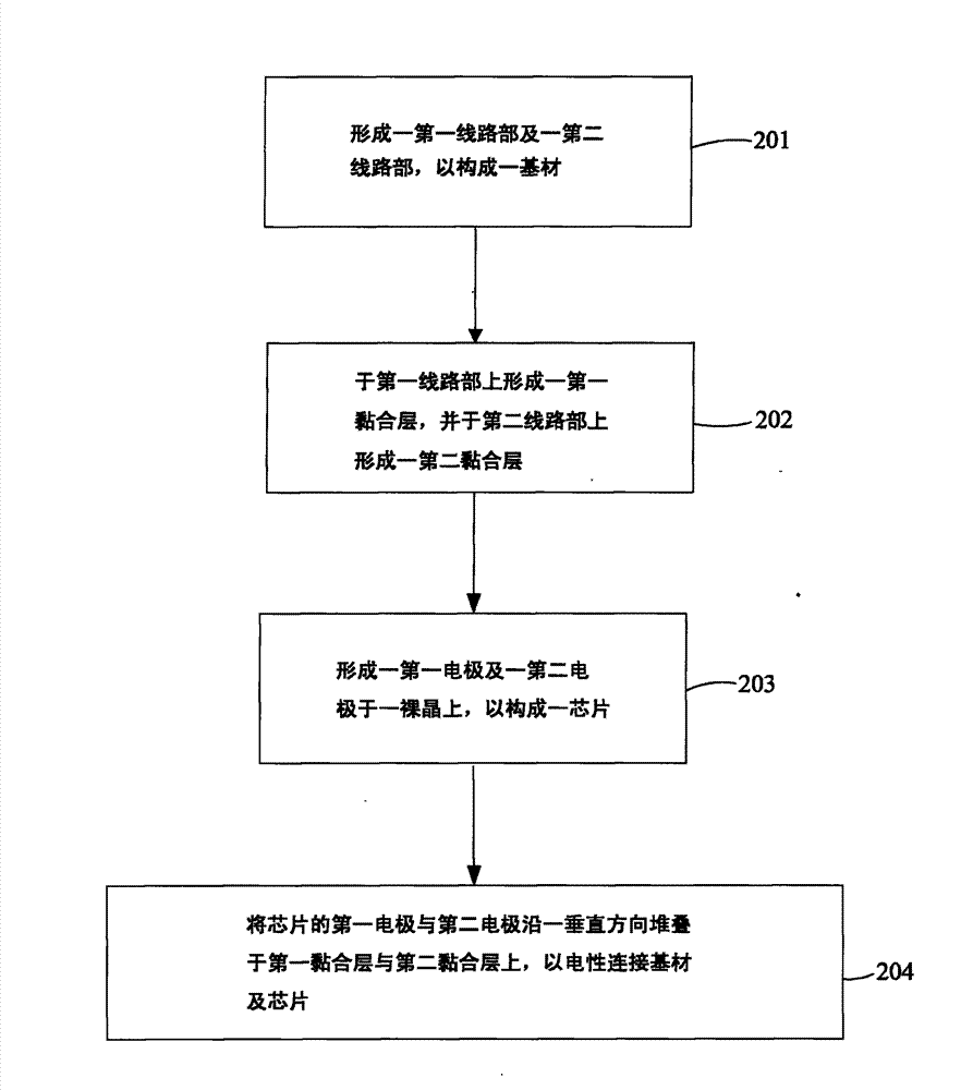
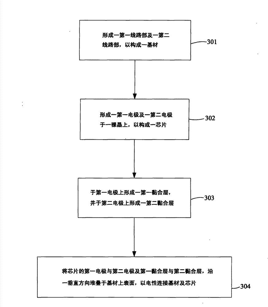

Image

  • Package structure and manufacturing method for the same
  • Package structure and manufacturing method for the same
  • Package structure and manufacturing method for the same

Examples


Embodiment Construction

[0012] The content of the present invention will be explained through the embodiments below. The present invention relates to a packaging structure and a manufacturing method thereof. It should be noted that in the following examples and accompanying drawings, the description of the implementation is only for the purpose of explaining the present invention, rather than directly limiting the present invention. Meanwhile, the following examples and accompanying drawings are not related to the present invention. All directly related elements are omitted and not shown; and the dimensional relationship among the elements in the drawings is only for easy understanding, and is not intended to limit the actual scale.

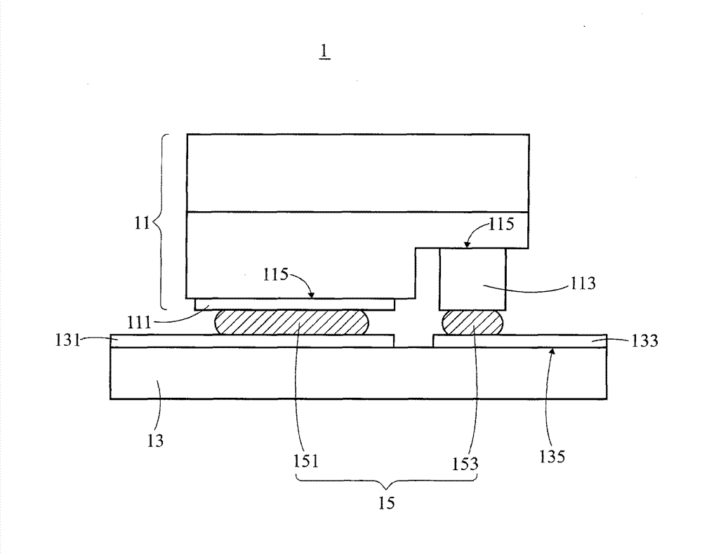
[0013] see figure 1 , which is a schematic diagram of a preferred embodiment of the packaging structure 1 of the present invention. The packaging structure 1 includes a chip 11 , a substrate 13 and an adhesive layer 15 , and the technical content of each component will...


PUM


Abstract

A package structure and a manufacturing method for the same are provided. The package structure includes a chip, a substrate and at least one adhesive layer. The chip has at least one electrode portion. The substrate has at least one circuit portion. The adhesive layer is disposed between the electrode portion and the circuit portion to form an electrical connection therebetween. The adhesive layer is a material, which comprises a metal compound, with a Negative Coefficient of Thermal Expansion (Negative CTE). Because of the material with a Negative CTE, the alignment shift can be avoided after the chip and the substrate are adhered together.

Description

technical field [0001] The invention relates to a package structure and a manufacturing method for the package structure. More specifically, the present invention relates to a packaging structure comprising a material with a negative thermal expansion coefficient and a manufacturing method for the packaging structure. Background technique [0002] In recent years, with the continuous maturity and development of semiconductor process technology, various high-performance electronic products have been continuously introduced, and the quality and performance of the most important chip in electronic products have been valued by the industry. Generally speaking, in the chip packaging process, nothing affects chip performance more than die bonding. This process uses an adhesive material to electrically connect the electrodes or bumps of the chip to the wiring on the substrate, so that electronic signals can be transmitted between the chip and external circuits on the substrate. K...

Claims


Application Information

Patent Timeline
Patent Type & Authority Applications(China)
IPC IPC(8): H01L33/62H01L33/00
CPCH01L33/641H01L33/00H01L33/62H01L2224/16225
Inventor 罗伟诚詹峯益姜崇义
Owner WALSIN LIHWA
Learn More